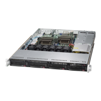
SC815 Chassis Manual
4-2
4-3
Chapter 4: System Interface
Power: The main power switch is used to apply or remove power from the power
supply to the server system. Turning off system power with this button removes the
main power but keeps standby power supplied to the system. Therefore, you must
unplug system before servicing.
Reset: The reset button is used to reboot the system.
4-2 Control Panel Buttons
There may be up to three push-buttons located on the front of the chassis. These
are (in order from left to right) a reset button and a power on/off button.
4-3 Control Panel LEDs
The control panel located on the front of the SC815 chassis has ve LEDs. These
LEDs provide you with critical information related to different parts of the system.
This section explains what each LED indicates when illuminated and any correc-
tive action you may need to take. Your chassis model will have some, but not all
of the LEDs listed.
UID (UB and WB Models Only): SC815 UB and WB chassis models include a UID
button. When used with a UID-compatible motherboard, the UID button is used to
turn on or off the blue light function of the the U-LED. Once the blue light is activated,
the unit can be easily located in very large racks and server banks.
Universal Information LED: The Universal Information LED is used to indated
fan failure, power failure, overheat condition, or to identify the unit within a large
rack installation. The feature requires a motherboard that supports the Universal
Information LED.
When this LED blinks red quickly, it indicates a fan failure and when blinking red
slowly a power failure. This LED will be blue when used for UID (Unit Identier).
When on continuously red, it indicates an overheat condition, which may be caused
by cables obstructing the airow in the system or the ambient room temperature
being too warm. See the table below for descriptions of the LED states.
Universal Information LED States
State Indication
Fast Blinking Red (1x/sec) Fan Fail
Solid Red CPU Overheat
Slow Blinking Red (1x/4 sec) Power Fail
Solid Blue Local UID Button Depressed
Blinking Blue IPMI-Activated UID
Note: Deactivating the UID LED must be performed in the same way it was acti-
vated. (If the UID LED was activated via IPMI, you can only turn the LED off via
IPMI and not with the UID button.)

 Loading...