5-18
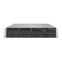
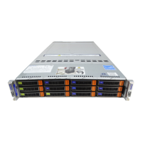
SUPERSERVER 6048R-TXR User's Manual
Unit Identier Switch
A Unit Identier (UID) switch is located
next to the VGA port. The Rear UID
LED (LED1) is located next to the UID
switch. The front UID LED connects
to pin 7 of the JF1 header. When you
press the UID switch, both front and
rear UID LED indicators will be turned
on. Press the UID switch again to turn
off both LED Indicators. These UID
Indicators provide easy identication
of a system unit that may be in need
of service.
Note: UID can also be triggered via
IPMI on the serverboard. For more
information on IPMI, please refer to
the IPMI User's Guide posted on our
website at http://www.supermicro.com.
UID Switch
Pin# Denition
1 Ground
2 Ground
3 Switch In
4 Switch In
UID LED
Status
Color/State Status
Blue: On Unit Identied
Universal Serial Bus (USB)
Two USB 3.0 (USB 4/5) and two USB 2.0 ports (USB 0/1) are located on the rear
I/O panel. A Type A USB connector (USB 6), and a USB header with two USB
connections (USB 7/8) provide a total of three USB 3.0 connections for front access.
In addition, a USB 2.0 header also provides two USB 2.0 support (USB 2/3) for front
access (cables are not included). See the tables below for pin denitions.
Backplane USB (3.0) 4/5
Pin Denitions
Pin# Denition Pin# Denition
1 +5V 5 +5V
2 USB_PN1 6 USB_PN0
3 USB_PP1 7 USB_PP0
4 Ground 8 Ground
USB (2.0) 0/1, 2/3
Pin Denitions
Pin# Denition Pin# Denition
1 +VBUS 6 SSTX+
2 SSRX- 7 GND_DRAIN
3 SSRX+ 8 D-
4 Ground 9 D+
5 SSTX- 10 n/a
Front Panel USB (3.0) USB 6, 7/8
Pin Denitions
Pin# Description Pin# Description
1 USB3.0_Front_VCC
2 USB3_RE_RXN6 19 USB3.0_Front_VCC
3 USB3_RE_RXP6 18 USB3_RE_RXN5
4 Ground 17 USB3_RE_RXP5
5 USB3_RE_TXN6 16 Ground
6 USB3_RE_TXP6 15 USB3_RE_TXN5
7 Ground 14 USB3_RE_TXP5
8 USB2_N8 13 Ground
9 USB2_P8 12 USB2_N9
10 Ground 11 USB2_P9
 Loading...