30
SuperServer 7089P-TR4T User's Manual
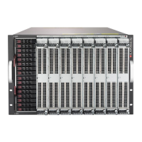
Figure 1-29. BPN-X11OPi Layout (Front)
5
G1
G1
G1
G1
G1
G1
G1
G1
G1
G1
G1
G1
G1
G1
G1
G1
G1
BPN-X11OPi
Rev.1.00
J76
JPWR1
JPWR10
JPWR3JPWR4
JPWR5
JPWR8
JPWR7
JPWR13
JPWR6
JPWR14
JPWR2
JPWR15
JPWR12
JPWR11
JPWR16
J50
JPWR9
U65
J7
J6
J31
J30
J3
J27
J26
J23
J22
J2
J18
J15
J14
J11
J10
J9
J8
J5
J4
J32
J29
J28
J25
J24
J21
J20
J17
J16
J13
J12
J1
JG3
JG4
JG5
JG6
JG7
JG8
JG9
JG10
JG1
JG12
JG11
JG13
JG14JG2
JG15
JG16
JG17
J48
J47
J19
FCP
PCI-E 3.0 X16
HPSXB1:CPU2 SLOT1
CPU BOARD SLOT1
CPU BOARD SLOT2
CPU BOARD SLOT3
CPU BOARD SLOT4
CPU BOARD SLOT5
CPU BOARD SLOT6
CPU BOARD SLOT7
CPU BOARD SLOT8
CUT
OFF
CUT OFF
CUT OFF
CUT OFF
CUT OFF
CUT OFF
CUT OFF
CUT OFF
CUT OFF
OFF
CUT
CUT
OFF
CUT OFF
CUT OFF
OFF
CUT
CUT OFF
OFF
CUT
CUT OFF
OFF
CUT
CUT OFF
OFF
CUT
CUT OFF
OFF
CUT
CUT OFF
OFF
CUT
CUT OFF
OFF
CUT
CUT OFF
CUT OFF
1
2
1
3
1
4
1
10
1
5
1
8
1
9
1
6
1
1
1
7
1
11
1
12
1
13
1
14
1
15
1
16
1
17
1
18
1
19
1
20
1
21
1
22
1
23
1
24
1
25
1
26
Major Components on the BPN-X11OPi Midplane
Components on the Front Side of the Midplane
The following section provides detailed information of the major components on the front side
of the BPN-X11OPi midplane. Please note that all CPU boards and HDD card are installed
on the front side of the midplane, and can be accessed from the front side of your system.
Major Front Side Components of the BPN-X11OPi Midplane
Major Components on the Front Side of the BPN-X11OPi
Item# Description Detailed Description
1 CPU BOARD SLOT1 CPU Board slot used for X11OPi Board 1
2 CPU BOARD SLOT2 CPU Board slot used for X11OPi Board 2
3 CPU BOARD SLOT3 CPU Board slot used for X11OPi Board 3
4 CPU BOARD SLOT4 CPU Board slot used for X11OPi Board 4
5 CPU BOARD SLOT5 CPU Board slot used for X11OPi Board 5
6 CPU BOARD SLOT6 CPU Board slot used for X11OPi Board 6
7 CPU BOARD SLOT7 CPU Board slot used for X11OPi Board 7
8 CPU BOARD SLOT8 CPU Board slot used for X11OPi Board 8
9 FCP (Front Control Panel ) Front Control Panel header
10 HPSXB1 (CPU2Slot1) 2 x PCI-E 3.0 x8 slot supported by CPU2 (for the AOM-X11OPi-HDD card)
11, 12 JPWR1/JPWR2 Power connectors 1/2 for X11OPi Board 1
13, 14 JPWR3/JPWR4 Power connectors 3/4 for X11OPi Board 2
15, 16 JPWR5/JPWR6 Power connectors 5/6 for X11OPi Board 3
17, 18 JPWR7/JPWR8 Power connectors 7/8 for X11OPi Board 4
19, 20 JPWR9/JPWR10 Power connectors 9/10 for X11OPi Board 5
21, 22 JPWR11/JPWR12 Power connectors 11/12 for X11OPi Board 6
23, 24 JPWR13/JPWR14 Power connectors 13/14 for X11OPi Board 7
25, 26 JPWR15/JPWR16 Power connectors 15/16 for X11OPi Board 8
 Loading...


