28
SuperServer E200-9A User's Manual
3.2 Headers and Connectors
Fan Headers
This motherboard has four 4-pin fan headers. Pins 1-3 of the fan headers are backward
compatible with the traditional 3-pin fans, but using 4-pin fans takes advantage of the fan
speed control via Pulse Width Modulation through the BMC. This allows the fan speeds to
Fan Header
Pin Denitions
Pin# Denition
1 Ground (Black)
2 +12V (Red)
3 Tachometer
4 PWM Control
Speaker
JD1 is the speaker header. Connect the cable of the external speaker to pins 1-4.
Speaker Connector
Pin Denitions
Pin# Denition
Pins 1-4 Speaker
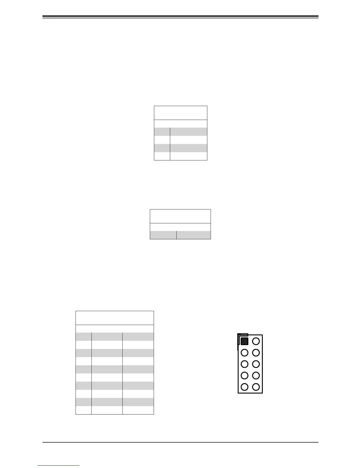
General Purpose I/O Header
JGPIO1 is a 10-pin general purpose I/O header located near the IPMI port. Each pin can be
expansion. The base address is 0xF040(D31:F4).
JGP1 Header
Pin Denitions
Pin# Denition
1 +5V +5V
2 Ground Ground
3 GP0 GPP_E0
4 GP1 GPP_F1
5 GP2 GPP_E1
6 GP3 GPP_F2
7 GP4 GPP_E2
8 GP5 GPP_F3
9 GP6 GPP_F0
10 GP7 GPP_F4
BIOS LICENSE
JTGLED1
JPW1
A2SDi-2C-HLN4F
REV:1.00
DESIGNED IN USA
BAR CODE
COM1
JPCIE1
JSD1
1
SRW1
SRW2
JUIDB
JPL1
JWD1
JPG1
JBR1
JPME2
JI2C1 JI2C2
PRESS FIT
JSAS1
PRESS FIT
JSAS2
JMD1
JB3
LED1
JD1
JSMB1
JGP1
1
JBT1
JPH1
JPV1
FANA
FAN1
FAN2
JF1
JTPM1
JL1
JRT4
JRT3
I-SATA2
I-SATA1 I-SATA3
I-SATA0
JUSB3A1
UIDLED1
A
LEDM1
FANA
FAN3
SUPERDOM
SATA DOM+POWER
8-11
4-7
I-SATA
I-SATA
IPMI LAN
DIMMA1
DIMMA2
DIMMB2
DIMMB1
CPU
ALWAYS POPULATE DIMMA1 FIRST
CPU SLOT7 PCI-E 3.0 X4
M.2:PCI-E 3.0 X2 / I-SATA
LAN4
INTRUSION
JD1:
1-4:SPEAKER
CHASSIS
JL1:
JPB1:BMC
1-2:ENABLE
2-3:DISABLE
1-2:ENABLE
JI2C1:
2-3:DISABLE
JI2C2:
1-2:ENABLE
2-3:DISABLE
1-2:NORMAL
JPME2:
2-3:ME MANUFACTURING MODE
RST
JF1
ON
PWR
2
NIC
OH/FFX
2-3:NMI
1-2:RST
JWD1:WATCH DOG
PWR
1 LED
HDDNIC
LED
JPI2C1
JBR1
1-2:NORMAL
2-3:BIOS RECOVERY
LAN2
USB0/1
USB2/3
USB4(3.0)
VGA
LAN1
LAN3
BT1
1 2
109