2-14
X10SLM+/X10SLL+ Motherboard Series User's Manual
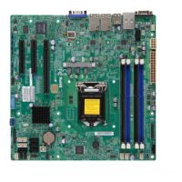
LE6
DIMM2
DIMM3
DIMM1
DIMM4
FAN2
FAN3
FAN4
FAN1
FANA
JBR1
JLED1
JWD1
JPL3
JPL4
JPL2
JPL1
J19 - RESERVED
LE3
LE5
LE4
J8
JPW2
J21
JI2C1
JI2C2
JL1
J31
J32
JS1
JS2
JS3
JUSB1
JPI2C1
JTPM1
U7
J12
J11
T-SGPIO2
JSD1
JSTBY1
B1
JBT1
JF1
J14
SW1
MH8
MH7
MH1
MH6
MH5
NMI
X
JTPM1:TPM/PORT80
JBR1:BIOS RECOVERY
1-2:NORMAL
2-3:BIOS RECOVERY
1-2:ENABLE
JPUSB1:USB4/5 WAKE UP
2-3:DISABLE
LAN4
LAN3
1-2:ENABLE
JPL2:LAN2
2-3:DISABLE
2-3:DISABLE
JPL4:LAN4
1-2:ENABLE
JPME2
1-2:NORMAL
2-3:ME MANUFACTURING MODE
2-3:ME RECOVERY
JPME1
1-2:NORMAL
COM2
FF
1-2:RST
2-3:NMI
JWD1:WATCH DOG
JSD1:SATA DOM POWER
_LAN
IPMI
1-2:ENABLE
2-3:DISABLE
JPL3:LAN3
JPL1:LAN1
2-3:DISABLE
1-2:ENABLE
JPI2C1:PWR I2C
VGA
COM1
USB0(3.0)
JBT1:CMOS CLEAR
LAN2
JL1
LAN1
DIMMB2
DIMMA2
JI2C1/JI2C2
USB4/5
CPU SLOT6 PCI-E 3.0 X8/16
2-3:DISABLE
1-2:ENABLE
CPU
OFF:DISABLE
ON:ENABLE
:CHASSIS INTRUSION
JF1
ON
LED
LED
PWR
HDD
NIC1
NIC2
OH/
X
RST
PWR
USB2/3(3.0)
I-SATA 3
I-SATA 4
I-SATA 1
I-SATA 0
I-SATA 5
CPU SLOT5 PCI-E 3.0 X8
PCH SLOT4 PCI-E 2.0 X2/4(INX8)
DIMMB1
DIMMA1
JPG1: VGA
J18 - RESERVED
I-SATA 2
SP1
Caution: 1) To avoid damaging the motherboard and its components, please do
not use a force greater than 8 lb/inch on each mounting screw during motherboard
installation. 2) Some components are very close to the mounting holes. Please take
precautionary measures to avoid damaging these components when installing the
motherboard to the chassis.
2-5 Motherboard Installation
All motherboards have standard mounting holes to t different types of chassis.
Make sure that the locations of all the mounting holes for both motherboard and
chassis match. Although a chassis may have both plastic and metal mounting fas-
teners, metal ones are highly recommended because they ground the motherboard
to the chassis. Make sure that the metal standoffs click in or are screwed in tightly.
Then use a screwdriver to secure the motherboard onto the motherboard tray.
Tools Needed
Philips Screwdriver
(1)
Standoffs (8)
Only if Needed
Philips Screws (8)
Location of Mounting Holes
 Loading...