2-36
X10SLM+/X10SLL+ Motherboard Series User's Manual
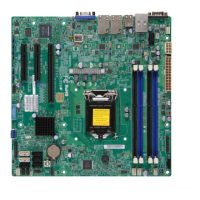
DIMM2
DIMM3
DIMM1
DIMM4
FAN4
FAN1
FANA
JBR1
JLED1
JWD1
JPG1
JPL3
JPL4
JPL2
JPL1
LE4
JPW2
J21
JI2C1
JI2C2
JL1
J31
J32
JS1
JS2
JS3
JUSB1
JPI2C1
JTPM1
U7
J12
J11
T-SGPIO1
T-SGPIO2
JSD1
JSTBY1
SW1
MH6
MH5
NMI
X
JTPM1:TPM/PORT80
JBR1:BIOS RECOVERY
1-2:NORMAL
2-3:BIOS RECOVERY
1-2:ENABLE
JPUSB1:USB4/5 WAKE UP
2-3:DISABLE
LAN4
LAN3
1-2:ENABLE
JPL2:LAN2
2-3:DISABLE
2-3:DISABLE
JPL4:LAN4
1-2:ENABLE
JPME2
1-2:NORMAL
2-3:ME MANUFACTURING MODE
2-3:ME RECOVERY
JPME1
1-2:NORMAL
COM2
USB1(3.0)
FF
1-2:RST
2-3:NMI
JWD1:WATCH DOG
USB8/9
USB12/13
JSD1:SATA DOM POWER
_LAN
IPMI
1-2:ENABLE
2-3:DISABLE
JPL3:LAN3
JPL1:LAN1
2-3:DISABLE
1-2:ENABLE
VGA
COM1
LAN2
LAN1
DIMMB2
DIMMA2
USB4/5
CPU SLOT6 PCI-E 3.0 X8/16
2-3:DISABLE
1-2:ENABLE
CPU
OFF:DISABLE
ON:ENABLE
:CHASSIS INTRUSION
JF1
ON
LED
LED
PWR
HDD
NIC1
NIC2
OH/
X
RST
PWR
USB2/3(3.0)
I-SATA3
I-SATA4
I-SATA1
I-SATA0
I-SATA5
CPU SLOT5 PCI-E 3.0 X8
PCH SLOT4 PCI-E 2.0 X2/4(INX8)
DIMMB1
DIMMA1
JPG1: VGA
J18 - RESERVED
I-SATA2
SP1
A. LAN1/2 LEDs
B. LAN3/4 LEDs
C. IPMI_LAN LEDs
A
B
LAN1/LAN2 LEDs
Two LAN ports (LAN1/LAN2) are
located on the I/O back panel of the
motherboard. Each Ethernet LAN port
has two LEDs. The yellow LED indi-
cates activity, while the Link LED may
be green, amber, or off to indicate
the speed of the connections. See
the tables at right for more informa-
tion. On the X10SLM+-LN4F, there
is an additional two LAN ports (LAN3/
LAN4).
2-9 Onboard Indicators
Activity
LED
Link
LED
LAN Ports 1/2/3/4 Link Indicator
LED Settings
LED Color Denition
Off No Connection or 10
Mbps
Amber 1 Gbps
Green 100 Mbps
LAN 1/2/3/4 Activity Indicator
LED Settings
Color Status Denition
Yellow Flashing Active
Dedicated IPMI LAN LEDs
A dedicated IPMI LAN port is also
located on the I/O back panel. The am-
ber LED on the right indicates connec-
tion and activity, while the green LED
on the left indicates the speed of the
connection. See the table on the right.
LAN 1/LAN 2
IPMI LAN
(X8ST3-F)
Activity LED
IPMI LAN
IPMI LAN Link Speed LED (Left) &
Connection Activity LED (Right)
LED Color/State Denition
Off Off No Connection
Activity Amber: Blinking Active
Speed Orange 1 Gbps
Speed Green 100 Mbps
Link Speed LED
C
A
B
 Loading...