Chapter 2: Installation
2-25
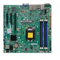
A. Fan 1 (CPU Fan)
B. Fan 2
C. Fan 3
D. Fan 4
E. Fan A
F. Chassis Intrusion
LE6
DIMM2
DIMM3
DIMM1
DIMM4
FAN2
FAN3
FAN4
FAN1
FANA
JBR1
JLED1
JWD1
JPL3
JPL4
JPL2
JPL1
J19 - RESERVED
LE3
LE5
LE4
J8
JPW2
J21
JI2C1
JI2C2
JL1
J31
J32
JS1
JS2
JS3
JUSB1
JPI2C1
JTPM1
U7
J12
J11
T-SGPIO1
T-SGPIO2
JSD1
JSTBY1
B1
JBT1
JF1
J14
SW1
MH8
MH7
MH1
MH6
MH5
NMI
X
JTPM1:TPM/PORT80
JBR1:BIOS RECOVERY
1-2:NORMAL
2-3:BIOS RECOVERY
1-2:ENABLE
JPUSB1:USB4/5 WAKE UP
2-3:DISABLE
LAN4
LAN3
1-2:ENABLE
JPL2:LAN2
2-3:DISABLE
2-3:DISABLE
JPL4:LAN4
1-2:ENABLE
JPME2
1-2:NORMAL
2-3:ME MANUFACTURING MODE
2-3:ME RECOVERY
JPME1
1-2:NORMAL
COM2
FF
1-2:RST
2-3:NMI
JWD1:WATCH DOG
JSD1:SATA DOM POWER
_LAN
IPMI
1-2:ENABLE
2-3:DISABLE
JPL3:LAN3
JPL1:LAN1
2-3:DISABLE
1-2:ENABLE
JPI2C1:PWR I2C
VGA
COM1
JBT1:CMOS CLEAR
LAN2
JL1
LAN1
DIMMB2
DIMMA2
JI2C1/JI2C2
USB4/5
CPU SLOT6 PCI-E 3.0 X8/16
2-3:DISABLE
1-2:ENABLE
CPU
OFF:DISABLE
ON:ENABLE
:CHASSIS INTRUSION
JF1
ON
LED
LED
PWR
HDD
NIC1
NIC2
OH/
X
RST
PWR
USB2/3(3.0)
I-SATA3
I-SATA4
I-SATA1
I-SATA0
I-SATA5
CPU SLOT5 PCI-E 3.0 X8
PCH SLOT4 PCI-E 2.0 X2/4(INX8)
DIMMB1
DIMMA1
JPG1: VGA
J18 - RESERVED
I-SATA2
SP1
Fan Header
Pin Denitions
Pin# Denition
1 Ground (Black)
2 2.5A/+12V
(Red)
3 Tachometer
4 PWM_Control
Fan Headers (Fan 1- Fan 4/Fan A)
The X10SLM+/X10SLL+ Motherboard Series
has ve fan headers (Fan 1-Fan 4, Fan A).
These fans are 4-pin fan headers. Although pins
1-3 of the fan headers are backward compatible
with the traditional 3-pin fans, we recommend
that 4-pin fans be used to take advantage of the
fan speed control via IPMI interface. This allows
the fan speeds to be automatically adjusted
based on the temperatures of the CPU or the
motherboard. Refer to the table on the right for
pin denitions.
A
B
C
Chassis Intrusion (JL1)
A Chassis Intrusion header is located at JL1 on
the motherboard. Attach the appropriate cable
from the chassis to inform you of a chassis intru-
sion when the chassis is opened.
Chassis Intrusion
Pin Denitions (JL1)
Pin# Denition
1 Intrusion Input
2 Ground
E
D
 Loading...