Do you have a question about the Supermicro X10SLM+-F and is the answer not in the manual?
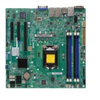
Overview of the X10SLM+/X10SLL+ Motherboard Series features and capabilities.
Describes the structure and content of the manual, outlining chapters and appendices.
Explains symbols and warnings used in the manual for proper installation and safety.
Provides a general introduction and checklist of items included with the motherboard.
Details the Intel C220/C222/C224 Express Chipset and its features.
Describes special features like recovery from AC power loss and PC health monitoring.
Explains the board's PC health monitoring capabilities, including voltage and fan status.
Explains Advanced Configuration and Power Interface (ACPI) features for power management.
Details power supply requirements, including ATX connectors and voltage.
Describes the Super I/O chip and its serial communication port capabilities.
Discusses advanced power management features like Intel Intelligent Power Node Manager.
Lists and describes the key features of the X10SLM+/X10SLL+ motherboard.
Illustrates the system architecture and component interconnections.
Industry-standard warnings to alert users to potential hazards during installation.
Provides crucial safety warnings and instructions for handling and disposing of batteries.
Instructions on the proper disposal of the product according to national laws and regulations.
Details precautions for handling static-sensitive components to prevent damage.
Lists measures to protect equipment from ESD and guides safe unpacking.
Step-by-step instructions for installing the CPU and its heatsink securely.
Detailed guide on how to correctly install the LGA1150 processor into the socket.
Instructions for mounting, connecting, and safely removing the CPU heatsink.
Step-by-step guide for installing DDR3 memory modules into the motherboard slots.
Covers DIMM installation, supported memory types, and population recommendations.
Instructions for installing the motherboard into a computer chassis.
Lists necessary tools, identifies mounting holes, and details installation steps.
Identifies and explains the various onboard connectors and I/O ports.
Details backplane ports and explains serial COM and video connections.
Describes USB ports, headers, and Ethernet ports with pin definitions.
Explains the UID switch and front panel controls for system identification and operation.
Defines pinouts for front panel buttons and indicators like NMI, Power, and LEDs.
Provides pin-out definitions for onboard headers and connectors.
Details the 24-pin ATX and 8-pin CPU power connectors and their pinouts.
Describes fan headers for cooling and the chassis intrusion header for security.
Explains internal buzzer, onboard power LED, DOM, and standby power headers.
Details SGPIO headers for general I/O and TPM/Port 80 headers for security.
Describes the Power SMB (I2C) connector and LAN LED headers.
Explains how to use jumpers to configure motherboard settings.
Explains jumper functionality and how to enable/disable Gigabit LAN ports.
Details clearing CMOS settings and enabling PCI Slot SMB support via jumpers.
Explains how to enable/disable Watch Dog timer and the onboard VGA connector.
Describes jumper settings for Management Engine (ME) recovery and manufacture mode.
Instructions for enabling BIOS recovery and LAN firmware upgrades using jumpers.
Explains the various onboard LEDs and their meanings.
Describes LAN port activity/link LEDs and dedicated IPMI LAN LEDs.
Explains onboard power, IPMI heartbeat, and UID LEDs for system status.
Details the onboard SATA connectors, types, and pin definitions.
Describes SATA 3.0 connections and supported RAID configurations.
Provides general procedures for troubleshooting system issues.
Steps to check before powering on the system to diagnose issues.
Steps to diagnose and resolve 'no power' issues.
Troubleshooting steps for systems that do not display video output.
Guidance on identifying and resolving memory-related errors.
Explains causes and solutions for losing BIOS setup configuration.
Steps to follow before contacting technical support for assistance.
Answers common questions about memory support and BIOS updates.
Instructions for removing and installing the onboard motherboard battery.
Step-by-step guide for safely removing the onboard battery.
Warnings and guidelines for the proper disposal of used batteries.
Step-by-step guide for installing a new onboard battery.
Introduces the AMI BIOS Setup Utility and its basic navigation.
Explains how to enter the BIOS setup utility and navigate its screens.
Details the main BIOS setup screen, its layout, and key legend.
Guide to configuring advanced system settings within the BIOS.
Configures boot behavior, error handling, and system restarts.
Controls power states, watchdog timer, power button behavior, and AC power loss recovery.
Displays detailed information about the CPU and its capabilities.
Settings for CPU features like Hyper-Threading, Virtualization, and cache prefetching.
Controls CPU AES, EIST, and Turbo Mode for performance and power.
Configures CPU core ratios, energy performance, VR current, and C-States.
Fine-tunes CPU C-States, latency, and power-saving features.
Configuration options for the motherboard chipset.
Settings related to the System Agent and VT-d capability.
Enables Intel Virtualization Technology for Direct I/O (VT-d).
Information and configuration for PCI-E slots and devices.
Configures ASPM for PCI-E slots and DMI links.
Displays detailed information about installed memory modules.
Sets the memory frequency limit for installed DIMM modules.
Configures EHCI controllers for USB 2.0 support.
Settings for legacy USB, port emulation, and XHCI/EHCI hand-off.
Configures SATA devices, controllers, and modes.
Enables or disables the built-in SATA controllers on the motherboard.
Selects the SATA mode (IDE, AHCI, RAID) for installed drives.
Configures SATA RAID, hot-plugging, device types, and port length values.
Configures PCI/PnP settings, including Above 4G Decoding.
Enables decoding of 64-bit devices above the 4GB address space.
Configures VGA palette, error generation, OPROM for PCI-E slots, and storage policy.
Selects priority between onboard and offboard video devices.
Enables PXE or UEFI for network stack support.
Configures ACPI sleep states, timers, and WHEA support.
Displays status information for ME BIOS, SPS, and ME firmware.
Configures Super IO chip settings, including serial ports.
Enables and configures onboard serial ports, including I/O and IRQ addresses.
Enables and configures console redirection for COM ports.
Configures terminal type, speed, flow control, data bits, parity, and stop bits.
Configures advanced redirection features and out-of-band management ports.
Manages SMBIOS event logging settings and log management.
Options to enable/disable SMBIOS event logging and manage log entries.
Defines MECI/METW for event logging and allows viewing the log.
Configuration and status of Intelligent Platform Management Interface (IPMI).
Displays IPMI firmware revision and the status of the IPMI firmware.
Manages the System Event Log (SEL) for IPMI, including enabling and erasing.
Configures EFI logging options and network settings for BMC/IPMI LAN.
Displays and configures MAC, IP, Subnet Mask, and Gateway addresses.
Configures the order of bootable devices for system startup.
Manages boot options, including UEFI BBS priorities and adding/deleting devices.
Configures system security settings, including administrator passwords.
Sets the administrator password required to enter BIOS setup.
Options for saving changes, discarding changes, and exiting the BIOS setup.
Exits BIOS setup without saving changes or saves changes and resets the system.
Restores defaults, saves/restores user settings, and sets boot override options.
Lists BIOS error beep codes and their corresponding error messages and descriptions.
Instructions for downloading and installing system drivers and utilities from Supermicro.
Guide to configuring SuperDoctor III for system monitoring and remote management.
Provides an overview of the Unified Extensible Firmware Interface (UEFI) BIOS.
Explains the structure of the UEFI BIOS image and recovery blocks.
Step-by-step instructions for recovering the BIOS using a USB device.
Introduces the Dual Boot Block feature for BIOS crisis recovery.
Explains the function of the BIOS boot block as a minimum BIOS loader.
Describes scenarios leading to BIOS boot block corruption and recovery methods.
Detailed steps to reboot the system using Jumper JBR1 for BIOS recovery.
| PS/2 ports quantity | 0 |
|---|---|
| IPMI LAN (RJ-45) port | Yes |
| USB 2.0 ports quantity | USB 2.0 ports have a data transmission speed of 480 Mbps, and are backwards compatible with USB 1.1 ports. You can connect all kinds of peripheral devices to them. |
| USB 3.2 Gen 1 (3.1 Gen 1) Type-A ports quantity | 2 |
| Maximum UDIMM memory | 32 GB |
| Number of DIMM slots | 4 |
| Supported DIMM module capacities | 1GB, 2GB, 4GB, 8GB |
| Memory voltage | 1.35, 1.5 V |
| Supported memory types | DDR3-SDRAM |
| Supported memory clock speeds | 1600 MHz |
| BIOS type | AMI |
| ACPI version | 5.0 |
| RAID levels | 0, 1, 5, 10 |
| Supported storage drive interfaces | SATA II, SATA III |
| Wi-Fi | No |
| LAN controller | Intel I210-AT, Realtek RTL8211E |
| Ethernet interface type | Gigabit Ethernet |
| On-board graphics card model | Aspeed AST2400 |
| Bundled software | - IPMI v2.0\\r - SuperDoctor III\\r - Watch Dog\\r - NMI |
| Processor socket | LGA 1150 (Socket H3) |
| Intel Xeon series | E3-1200 |
| Processor manufacturer | Intel |
| Motherboard chipset | Intel® C224 |
| Motherboard form factor | micro ATX |
| Width | 244 mm |
|---|