45
Chapter 2: Installation
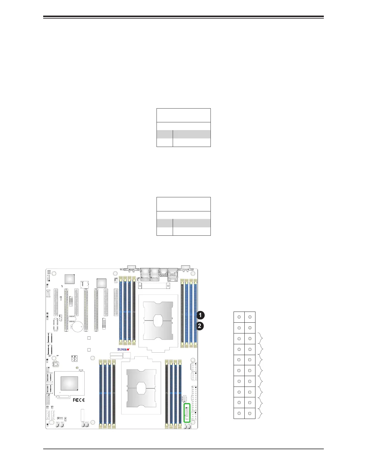
Power Button
UID LED
NIC1 Active LED
Reset Button
HDD LED
PWR LED
3.3V Stby
3.3V Stby
Ground
19
X
Ground
X
3.3V Stby
20
12
Ground
Power Fail LED
NIC2 Active LED
NMI
3.3V
3.3V
OH/PWR/Fail/Fan Fail LED
1
2
1. PWR Button
2. Reset Button
Reset Button
Pin Defi nitions (JF1)
Pins Defi nition
3 Reset
4 Ground
Power Button
Pin Defi nitions (JF1)
Pins Defi nition
1 Signal
2 Ground
Power Button
The Power Button connection is located on pins 1 and 2 of JF1. Momentarily contacting
both pins will power on/off the system. This button can also be confi gured to function as a
suspend button (with a setting in the BIOS - see Chapter 4). To turn off the power when the
system is in the suspend mode, press the button for 4 seconds or longer. Refer to the table
below for pin defi nitions.
Reset Button
The Reset Button connection is located on pins 3 and 4 of JF1. Attach it to a hardware reset
switch on the computer case to reset the system. Refer to the table below for pin defi nitions.
IPMI CODE
+
BIOS LICENSE
MAC CODE
X11DPH-i
REV: 1.10
BAR CODE
LEDM1
JUIDB1
JHSSI
JPWR4
JPWR2
JPWR1
JSD1
JSD2
JSDCARD1
SATA2
SATA1
MH4
MH11
T-SGPIO1
JNCSI
JRK1
JTPM1
JPWR3
JF1
JD1
JL1
JSTBY1
BT1
JPME2
JWD1
JIPMB1
LE1
LE4
LE3
JBT1
FAN6
FAN5
FANB
FANA
FAN4 FA N3
FAN2
FAN1
ASPEED
AST2500
LAN
CTRL
Intel
PCH
LE2
P2-DIMMF1
P2-DIMME1
P2-DIMMD1
P2-DIMMD2
P1-DIMMC1
P1-DIMMB1
P1-DIMMA1
P1-DIMMA2
P2-DIMMA2
P2-DIMMA1
P2-DIMMB1
P2-DIMMC1
P1-DIMMD2
P1-DIMMD1
P1-DIMME1
P1-DIMMF1
Battery
BMC
BIOS
M.2-C2
M.2-C1
CPU1-HSSI GPIO
USB 4/5(3.0)
USB 6 (3.0)
S-SATA1
S-SATA0
I- SATA 4~ 7
I- SATA 0~ 3
CPU1 SLOT1 PCI-E 3.0 x8
CPU2 SLOT2 PCI-E 3.0 x16
CPU1 SLOT3 PCI-E 3.0 x8
CPU2 SLOT4 PCI-E 3.0 x16
CPU2 SLOT5 PCI-E 3.0 x16
CPU1 SLOT6 PCI-E 3.0 x8
CPU1 SLOT7 PCI-E 3.0 x8
VGA
LAN2
LAN1
USB 2/3(3.0)
USB 0/1(3.0)
IPMI_LAN
COM1
JP4
CPU2
CPU1
 Loading...


