46
Super X11DPH-i/X11DPH-T/X11DPH-Tq User's Manual
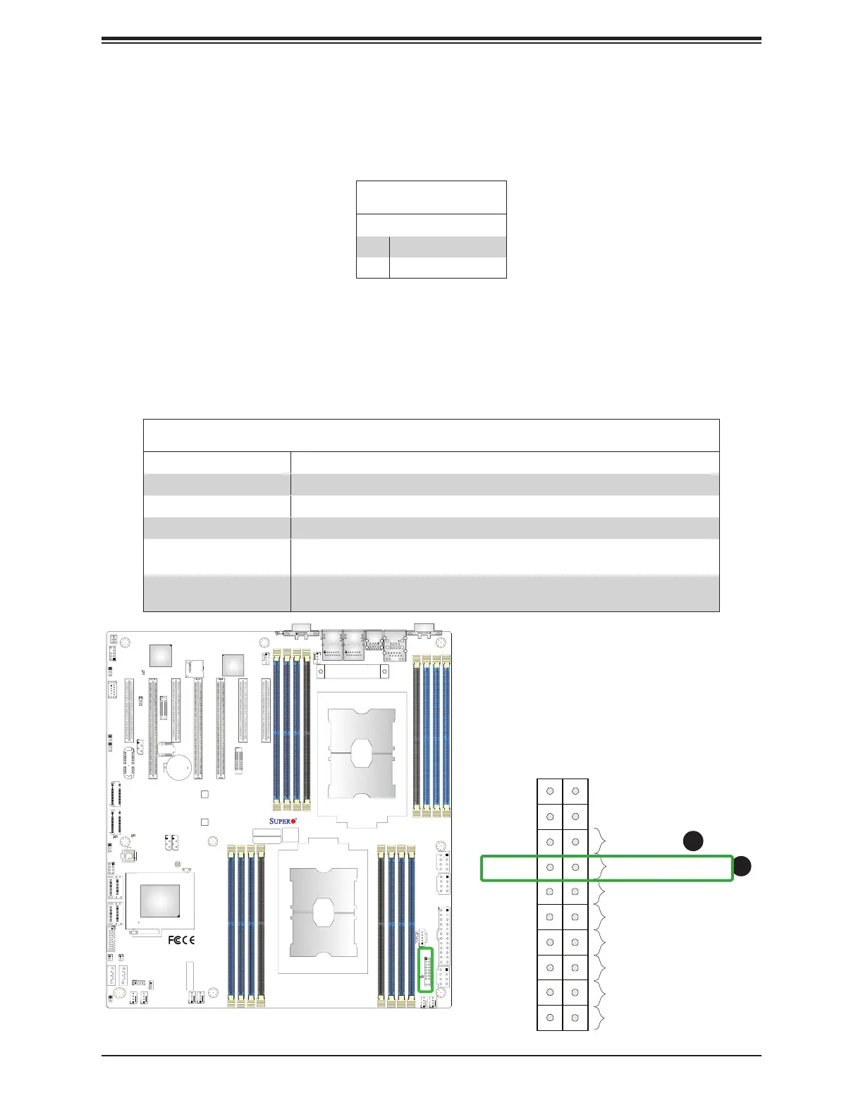
Power Button
UID LED
NIC1 Active LED
Reset Button
HDD LED
PWR LED
3.3V Stby
3.3V Stby
Ground
19
X
Ground
X
3.3V Stby
20
12
Ground
Power Fail LED
NIC2 Active LED
NMI
3.3V
3.3V
OH/PWR/Fail/Fan Fail LED
Power Fail LED
The Power Fail LED connection is located on pins 5 and 6 of JF1. Refer to the table below
for pin defi nitions.
Power Fail LED
Pin Defi nitions (JF1)
Pin# Defi nition
5 3.3V
6 PWR Supply Fail
1. Power Fail LED
2. UID/OH/PWR Fail/Fan Fail LED
1
2
IPMI CODE
+
BIOS LICENSE
MAC CODE
X11DPH-i
REV: 1.10
BAR CODE
LEDM1
JUIDB1
JHSSI
JPWR4
JPWR2
JPWR1
JSD1
JSD2
JSDCARD1
SATA2
SATA1
MH4
MH11
T-SGPIO1
JNCSI
JRK1
JTPM1
JPWR3
JF1
JD1
JL1
JSTBY1
BT1
JPME2
JWD1
JIPMB1
LE1
LE4
LE3
JBT1
FAN6
FAN5
FANB
FANA
FAN4 FA N3
FAN2
FAN1
ASPEED
AST2500
LAN
CTRL
Intel
PCH
LE2
P2-DIMMF1
P2-DIMME1
P2-DIMMD1
P2-DIMMD2
P1-DIMMC1
P1-DIMMB1
P1-DIMMA1
P1-DIMMA2
P2-DIMMA2
P2-DIMMA1
P2-DIMMB1
P2-DIMMC1
P1-DIMMD2
P1-DIMMD1
P1-DIMME1
P1-DIMMF1
Battery
BMC
BIOS
M.2-C2
M.2-C1
CPU1-HSSI GPIO
USB 4/5(3.0)
USB 6 (3.0)
S-SATA1
S-SATA0
I- SATA 4~ 7
I- SATA 0~ 3
CPU1 SLOT1 PCI-E 3.0 x8
CPU2 SLOT2 PCI-E 3.0 x16
CPU1 SLOT3 PCI-E 3.0 x8
CPU2 SLOT4 PCI-E 3.0 x16
CPU2 SLOT5 PCI-E 3.0 x16
CPU1 SLOT6 PCI-E 3.0 x8
CPU1 SLOT7 PCI-E 3.0 x8
VGA
LAN2
LAN1
USB 2/3(3.0)
USB 0/1(3.0)
IPMI_LAN
COM1
JP4
CPU2
CPU1
Information LED (UID/OH/PWR Fail/Fan Fail LED)
Pin Defi nitions (Pin 7 & Pin 8 of JF1)
Status Description
Solid red An overheat condition has occurred. (This may be caused by cable congestion).
Blinking red (1Hz) Fan failure: check for an inoperative fan.
Blinking red (0.25Hz) Power failure: check for a non-operational power supply
Solid blue Local UID is activated. Use this function to locate a unit in a rack mount
environment that might be in need of service.
Blinking blue (300 msec) Remote UID is on. Use this function to identify a unit from a remote location that
might be in need of service.
OH/Fan Fail/PWR Fail/UID LED
Connect an LED cable to pins 7 and 8 of the Front Control Panel (JF1) to use the UID/
Overheat/Fan Fail/PWR Fail LED connections. Pin 7 of JF1 (blue LED) is used as Front UID
LED. Pin 8 of JF1 (red LED) provides warnings for possible overheating, power failure, or
fan failure. Refer to the tables below for more information.
 Loading...


