35
Chapter 2: Installation
JTPM1
SAN MAC
SAS CODE
PRESS FIT
JPWR3
JSD2
JSD1
JBT1
JNVI2C1
JRK1
MH11
MH10
JSTBY1
BT1
+
LEDS1
JD1
JP2
JP3
I-SGPIO1
S-SGPIO1
I-SGPIO2
I-SATA3
I-SATA2
I-SATA1
I-SATA0
S-SATA1
S-SATA0
JPWR2
JPWR1
SXB2
IPMI CODE
FAN7
FAN5
FAN4
LE2
LEDM1
LE3
LE1
JP4
JPSAS1
JPS1
JP1
JPG1
JWD1
JPME2
JPTG1
JOH1
JF1
JPI2C1
BIOS LICENSE
DESIGNED IN USA
MAC CODE
X11SPW-CTF
REV:1.02
BAR CODE
M.2 PCI-E 3.0 X4
USB6
USB4/5
SXB1C
SXB1B
SXB1A
USB10/11(3.0)
JIPMB1
USB7/8(3.0)
USB9(3.0)
USB2/3
COM2
I-SATA 4-7
LAN2
VGA
CPU
LAN1
DIMMB1
LEDLED12LEDFAIL
ON
DIMMA1
NMIXPWRHDDNICNICUIDPSRSTPWR
DIMMF1
DIMME1
DIMMD1
DIMMC1
IPMI_LAN
USB0/1
COM1
SP1
LSI3008
(-CTF only)
Intel
C622
ASpeed
AST2500
Intel
X557
JUIDB1
JL1
L-SAS0-3
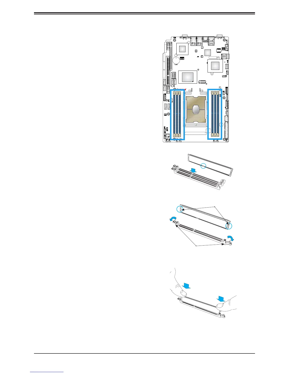
DIMM Installation
1. Insert the desired number of DIMMs
into the memory slots in the following
order: DIMMA1, DIMMD1, DIMMB1,
DIMME1, DIMMC1, DIMMF1. For the best
performance, please use the memory
modules of the same type and speed.
2. Push the release tabs outwards on both
ends of the DIMM slot to unlock it.
3. Align the key of the DIMM module with the
receptive point on the memory slot.
4. Align the notches on both ends of the
module against the receptive points on the
ends of the slot.
5. Press the notches on both ends of the
module straight down into the slot until the
module snaps into place.
6. Press the release tabs to the lock positions
to secure the DIMM module into the slot.
DIMM Removal
Press both release tabs on the ends of the
DIMM module to unlock it. Once the DIMM
module is loosened, remove it from the
memory slot.
Release Tabs
Notches
Press both notches
straight down into
the memory slot.

 Loading...


