43
Chapter 2: Installation
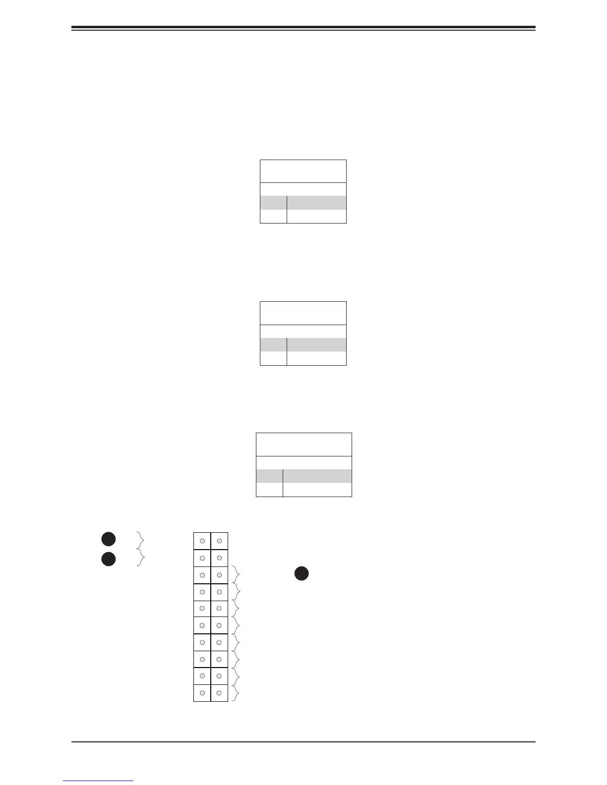
Power Button
The Power Button connection is located on pins 1 and 2 of JF1. Momentarily contacting both
pins will power on/off the system. This button can also be congured to function as a suspend
button (with a setting in the BIOS - see Chapter 4). To turn off the power in the suspend
mode, press the button for at least 4 seconds. Refer to the table below for pin denitions.
Reset Button
The Reset Button connection is located on pins 3 and 4 of JF1. Attach it to a hardware reset
switch on the computer case to reset the system. Refer to the table below for pin denitions.
1. PWR Button
2. Reset Button
3. Power Fail
Power Button
UID LED
NIC1 Active LED
Reset Button
HDD LED
PWR LED
Reset
PWR
3.3V Stby
3.3V Stby
3.3V Stby
Ground
19
X
Ground
X
3.3V Stby
3.3 V
5V Stby
20
1 2
Ground
Power Fail LED
NIC2 Active LED
NMI
1
2
Power Button
Pin Denitions (JF1)
Pins Denition
1 Signal
2 Ground
Reset Button
Pin Denitions (JF1)
Pins Denition
3 Reset
4 Ground
Power Fail LED
The Power Fail LED connection is located on pins 5 and 6 of JF1. Refer to the table below
for pin denitions.
PWR Fail LED
Pin Denitions (JF1)
Pins Denition
5 3.3V
6 Power Fail
3

 Loading...


