40
X11SPW-CTF/-TF User's Manual
JTPM1
SAN MAC
SAS CODE
PRESS FIT
JPWR3
JSD2
JSD1
JBT1
JNVI2C1
JRK1
MH11
MH10
JSTBY1
BT1
+
LEDS1
JD1
JP2
JP3
I-SGPIO1
S-SGPIO1
I-SGPIO2
I-SATA3
I-SATA2
I-SATA1
I-SATA0
S-SATA1
S-SATA0
JPWR2
JPWR1
SXB2
IPMI CODE
FAN7
FAN5
FAN3
FAN4
FAN2
FAN1
LE2
LEDM1
LE3
LE1
JP4
JPSAS1
JPS1
JP1
JPG1
JWD1
JPME2
JPTG1
JOH1
JF1
JPI2C1
BIOS LICENSE
DESIGNED IN USA
MAC CODE
X11SPW-CTF
REV:1.02
BAR CODE
M.2 PCI-E 3.0 X4
USB6
USB4/5
SXB1C
SXB1B
SXB1A
USB10/11(3.0)
JIPMB1
USB7/8(3.0)
USB9(3.0)
USB2/3
COM2
I-SATA 4-7
LAN2
VGA
CPU
LAN1
DIMMB1
LEDLED12LEDFAIL
ON
DIMMA1
NMIXPWRHDDNICNICUIDPSRSTPWR
DIMMF1
DIMME1
DIMMD1
DIMMC1
IPMI_LAN
USB0/1
COM1
SP1
LSI3008
(-CTF only)
Intel
C622
ASpeed
AST2500
Intel
X557
JUIDB1
JL1
L-SAS0-3
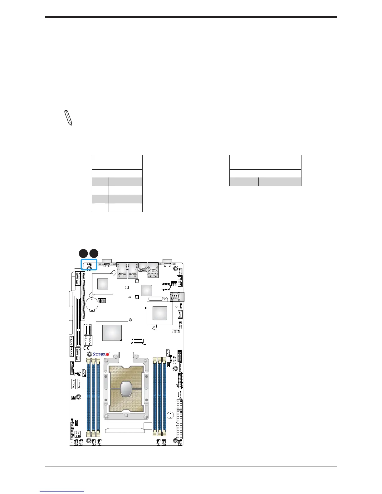
Unit Identier Switch/UID LED Indicator
A Unit Identier (UID) switch and an LED Indicator are located on the motherboard. The UID
switch is located at JUIDB1, which is next to the VGA port on the back panel. The UID LED
(LE1) is located next to the UID switch. When you press the UID switch, the UID LED will
be turned on. Press the UID switch again to turn off the LED indicator. The UID Indicator
provides easy identication of a system unit that may be in need of service.
Note: UID can also be triggered via IPMI on the motherboard. For more information
on IPMI, please refer to the IPMI User's Guide posted on our website at http://www.
supermicro.com.
UID Switch
Pin Denitions
Pin# Denition
1 Ground
2 Ground
3 Button In
4 Button In
UID LED
Pin Denitions
Color Status
Blue: On Unit Identied
1
2
1. UID Switch
2. UID LED

 Loading...


