26
X11SSH-GF/-GTF (-1585/-1585L) User's Manual
SAN MAC
DESIGNED IN USA
BIOS LICENSE
+
+
MH10
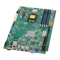
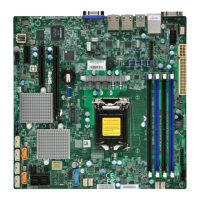
X11SSH-GF-1585L
REV:1.01
MAC CODE
IPMI CODE
BAR CODE
JSD2
JSD1
JSTBY1
JTPM1
LED2
LEDM1
JPWR2
JPWR1
J23
MH8
MH9
JUIDB1
SP1
JD1
J3
JPI2C1
JL1
JBT1
I-SATA2
I-SATA3
I-SATA5
I-SATA4
I-SATA7
I-SATA6
JF1
LED1
BAT1
JPL1
JVRM2
JWD1
JPME2
JVR1
JPB1
JVRM1
JPG1
J24
JI2C2
JLED1
JBR1
JI2C1
I-SGPIO2
I-SGPIO1
FANA
FAN3
FAN2
FAN1 (CPU FAN)
FAN4
PCH SLOT4 PCI-E 3.0 X4 (IN X8)
Intel®
C236
IPMI_LAN
USB10/11 (3.0)
USB2/3
CPU SLOT5 PCI-E 3.0 X8
USB6/7USB4/5
M.2 CONNECTOR
CPU SLOT6 PCI-E 3.0 X8 (IN X16)
USB12 (3.0)
VGA
LAN2
DIMMB1
LAN1
DIMMB2
DIMMA2
DIMMA1
CPU
USB8/9
(3.0)
USB0/1
NMI
LED
X
1 LED2FAIL LED
RST
JF1
ON
PWRNIC HDDNICPS UIDPWR
COM2
COM1
SO-DIMM Installation
1. Insert SO-DIMM modules in the following
order: DIMMA1, DIMMB1, DIMMA2, and
DIMMB2. For the system to work properly,
please use memory modules of the same
type and speed.
2. Position the bottom key of the SO-DIMM
module so that it aligns with the receptive
point on the slot. Take note of the side
notches of the memory module and the
locking clips of the socket.
3. Insert the SO-DIMM module straight down.
4. Press down until the module locks into
place. The side clips will automatically
secure the SO-DIMM module, locking it into
proper place.
Align
SO-DIMM Removal
1. Gently push the side clips near both ends
away from the module. Pull the SO-DIMM
module up to remove it from the slot.
 Loading...
