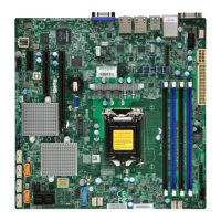
52
X11SSH-GF/-GTF (-1585/-1585L) User's Manual
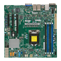
2.8 LED Indicators
SAN MAC
DESIGNED IN USA
BIOS LICENSE
+
+
MH10
X11SSH-GF-1585L
REV:1.01
MAC CODE
IPMI CODE
BAR CODE
JSD2
JSD1
JSTBY1
JTPM1
LED2
LEDM1
JPWR2
JPWR1
J23
MH8
MH9
JUIDB1
SP1
JD1
J3
JPI2C1
JL1
JBT1
I-SATA2
I-SATA3
I-SATA5
I-SATA4
I-SATA7
I-SATA6
JF1
LED1
BAT1
JPL1
JVRM2
JWD1
JPME2
JVR1
JPB1
JVRM1
JPG1
J24
JI2C2
JLED1
JBR1
JI2C1
I-SGPIO1
FANA
FAN3
FAN2
FAN1 (CPU FAN)
FAN4
PCH SLOT4 PCI-E 3.0 X4 (IN X8)
Intel®
C236
IPMI_LAN
USB10/11 (3.0)
USB2/3
CPU SLOT5 PCI-E 3.0 X8
USB6/7USB4/5
M.2 CONNECTOR
CPU SLOT6 PCI-E 3.0 X8 (IN X16)
USB12 (3.0)
VGA
LAN2
DIMMB1
LAN1
DIMMB2
DIMMA2
DIMMA1
CPU
USB8/9
(3.0)
USB0/1
NMI
LED
X
1 LED2FAIL LED
RST
JF1
ON
PWRNIC HDDNICPS UIDPWR
COM2
COM1
1
1. UID LED
2. Onboard Power LED
2
Onboard Power LED
LED2 is an Onboard Power LED. When this LED is lit, it means power is present on the
motherboard. In suspend mode, this LED will blink on and off. Turn off the system and unplug
the power cord before removing or installing components.
Onboard Power LED Indicator
LED Color Denition
Off
System Off (power
cable not connected)
Green System On
Unit ID LED
A rear UID LED indicator at LED1 is located next to the I/O back panel. The UID indicator
provides easy identiication of a system unit that may be in need of service. Refer to the
table for the LED status.
UID LED Indicator
LED Color Denition
Blue: On Unit Identied
 Loading...
