32
X11SSL-CF/-nF User Manual
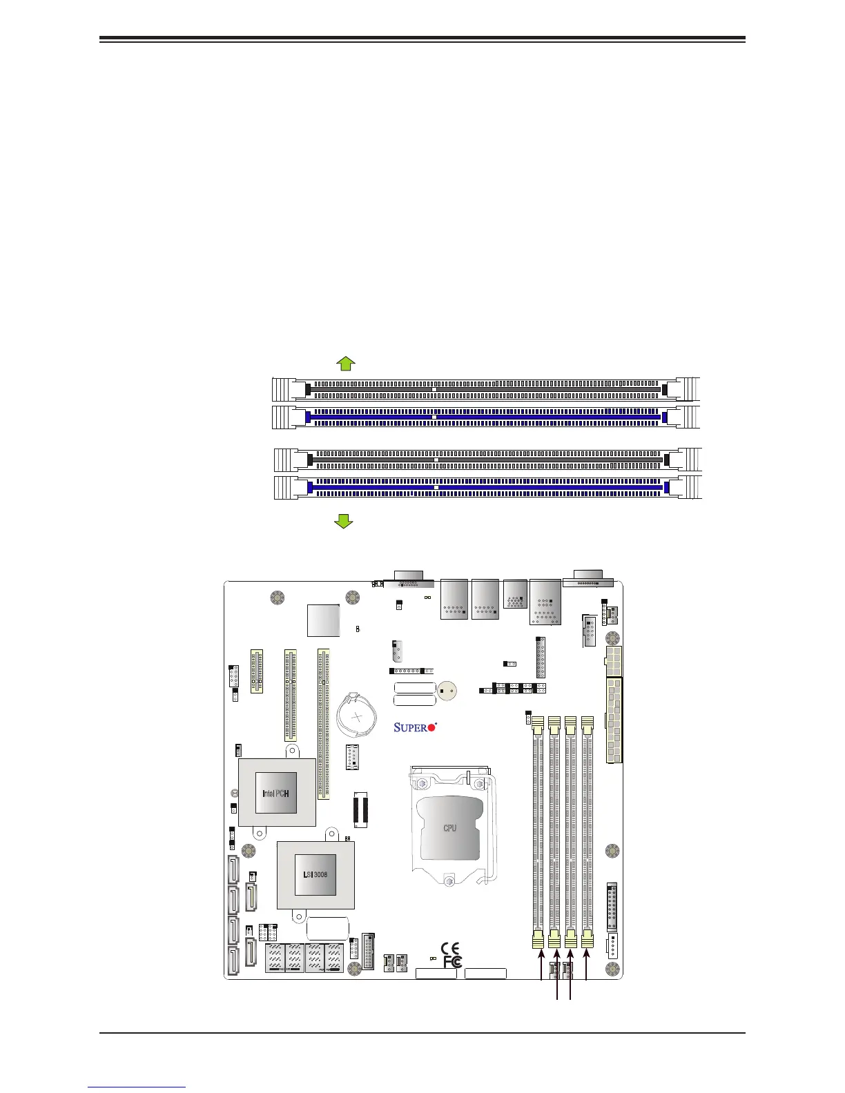
DIMM Module Population Sequence
When installing memory modules, the DIMM slots should be populated in the following order:
DIMMB2, DIMMA2, DIMMB1, DIMMA1.
• Always use DDR4 DIMM modules of the same type, size and speed.
• Mixed DIMM speeds can be installed. However, all DIMMs will run at the speed of the
slowest DIMM.
• The motherboard will support odd-numbered modules (1 or 3 modules installed). However,
for best memory performance, install DIMM modules in pairs to activate memory interleav-
ing.
DIMMB2 (Blue Slot)
DIMMA2 (Blue Slot)
Towards the edge of the motherboard
Towards the CPU
DIMMA1
DIMMB1
JPWR2
JPWR1
BMC
Intel PCH
IPMI_LAN
USB 0/1
JPWR2
USB 6/7
(3.0)
LAN 1
LAN 2
VGA
JTPM1
JPL1
JPL2
JD1
LED BMC
JIPMB1
JOH1
LE1
JUIDB1
USB 8 (3.0)
LED S1
LED PWR
FAN3
FANA
USB 4/5
USB 9/10 (3.0)
JSD1
I-SGPIO2
I-SGPIO1
JSD2
JL1
JBT1
JSTBY1
JPS1
X11SSL-CF_(-nF)
REV:1.01
Designed in the USA
SP1
JPG1
JBR1
JPME2
JPB1
JI2C2
SP1
JI2C1
JF1
JPI2C1
FAN1
FAN2
USB 2/3
PCH SLOT4 PCI-E 3.0 x1
PCH SLOT5 PCI-E 3.0 x4(in x8)
CPU SLOT6 PCI-E 3.0 x8(in x16)
I-SATA1
I-SATA4
I-SATA0
JWD1
DIMMB2
DIMMB1
DIMMA2
DIMMA1
JSAS1
JNVME1
LSI 3008
CPU
BT1
MEGERAC
LICENSE
DIMMA1
DIMMA2
DIMMB1
DIMMB2

 Loading...


