33
Chapter 2: Installation
JPWR2
JPWR1
BMC
Intel PCH
IPMI_LAN
USB 0/1
JPWR2
USB 6/7
(3.0)
LAN 1
LAN 2
JTPM1
JPL1
JPL2
JD1
LED BMC
JIPMB1
JOH1
LE1
JUIDB1
USB 8 (3.0)
LED S1
LED PWR
FAN3
FANA
USB 4/5
USB 9/10 (3.0)
JSD1
I-SGPIO2
I-SGPIO1
JSD2
JL1
JBT1
JSTBY1
JPS1
X11SSL-CF_(-nF)
REV:1.01
Designed in the USA
SP1
JPG1
JBR1
JPME2
JPB1
JI2C2
SP1
JI2C1
JF1
JPI2C1
FAN1
FAN2
USB 2/3
PCH SLOT4 PCI-E 3.0 x1
PCH SLOT5 PCI-E 3.0 x4(in x8)
CPU SLOT6 PCI-E 3.0 x8(in x16)
I-SATA5
I-SATA1
I-SATA4
I-SATA3 I-SATA2
I-SATA0
JWD1
DIMMB2
DIMMB1
DIMMA2
DIMMA1
JSAS1
JNVME1
LSI 3008
CPU
BT1
MEGERAC
LICENSE
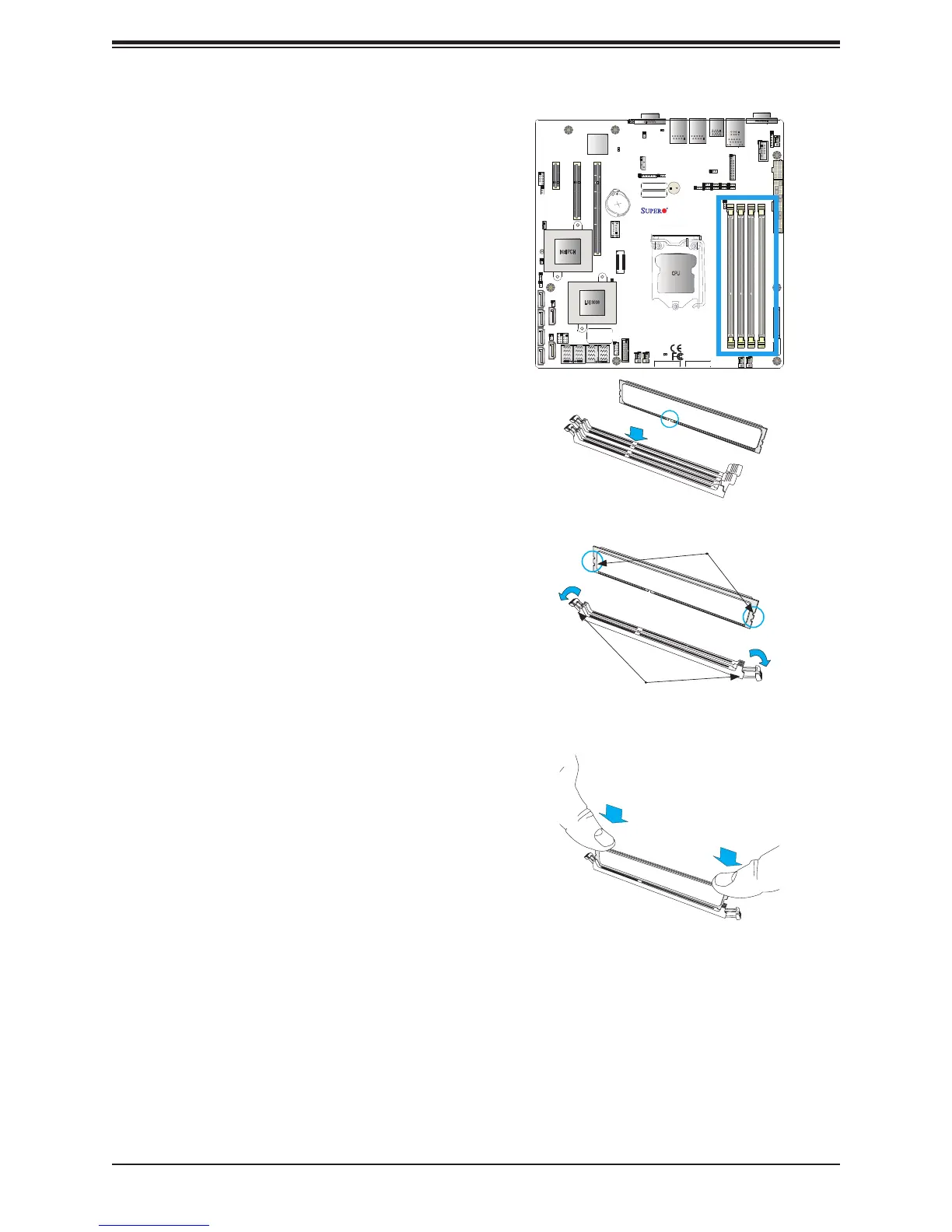
DIMM Installation
1. Insert the desired number of DIMMs into
the memory slots, starting with DIMMB2
(Channel B, Slot 2, blue slot). For best
performance, please use the memory
modules of the same type and speed in
the same bank.
2. Push the release tabs outwards on both
ends of the DIMM slot to unlock it.
3. Align the key of the DIMM module with the
receptive point on the memory slot.
4. Align the notches on both ends of the
module against the receptive points on the
ends of the slot.
5. Use two thumbs together to press the
notches on both ends of the module
straight down into the slot until the module
snaps into place.
6. Press the release tabs to the lock positions
to secure the DIMM module into the slot.
DIMM Removal
Press both release tabs on the ends of the
DIMM module to unlock it. Once the DIMM
module is loosened, remove it from the
memory slot.
Release Tabs
Notches
Press both notches
straight down into
the memory slot.

 Loading...


