47
Chapter 2: Installation
JPWR2
JPWR1
BMC
Intel PCH
IPMI_LAN
USB 0/1
JPWR2
USB 6/7
(3.0)
LAN 1
LAN 2
VGA
JTPM1
JPL1
JPL2
JD1
LED BMC
JIPMB1
JOH1
LE1
JUIDB1
USB 8 (3.0)
LED S1
LED PWR
FAN3
FANA
USB 4/5
USB 9/10 (3.0)
JSD1
I-SGPIO2
I-SGPIO1
JSD2
JL1
JBT1
JSTBY1
JPS1
X11SSL-CF_(-nF)
REV:1.01
Designed in the USA
SP1
JPG1
JBR1
JPME2
JPB1
JI2C2
SP1
JI2C1
JF1
JPI2C1
FAN1
FAN2
USB 2/3
PCH SLOT4 PCI-E 3.0 x1
PCH SLOT5 PCI-E 3.0 x4(in x8)
CPU SLOT6 PCI-E 3.0 x8(in x16)
I-SATA5
I-SATA1
I-SATA4
I-SATA3 I-SATA2
I-SATA0
JWD1
DIMMB2
DIMMB1
DIMMA2
DIMMA1
JSAS1
JNVME1
LSI 3008
CPU
BT1
MEGERAC
LICENSE
1
2
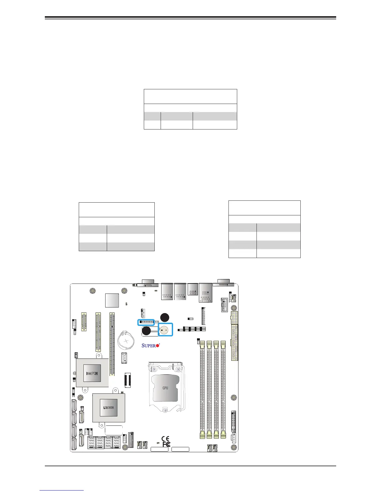
1. Internal Buzzer
2. Speaker Header
Internal Speaker/Buzzer
The Internal Speaker (SP1) can be used to provide audible notications using various beep
codes. Refer to the table below for pin denitions. Refer to the layout below for the location
of the internal buzzer.
Internal Buzzer
Pin Denitions
Pin# Denition
1 Pos (+) Beep In
2 Neg (-) Alarm Speaker
Power LED/Speaker
Pins 1-3 of JD1 are used for power LED indication, and pins 4-7 are for the speaker. Please
note that the speaker connector pins (4-7) are used with an external speaker. If you wish to
use the onboard speaker, you should close pins 6-7 with a cap. Refer to the tables below
for pin denitions.
PWR LED Connector
Pin Denitions
Pin Setting Denition
1 JD1_PIN1
2 FP_PWR_LED
3 FP_PWR_LED
Speaker Connector
Pin Denitions
Pin Setting Denition
4 P5V
5 Key
6 R_SPKPIN_N
7 R_SPKPIN

 Loading...


