49
Chapter 2: Installation
JPWR2
JPWR1
BMC
Intel PCH
IPMI_LAN
USB 0/1
JPWR2
USB 6/7
(3.0)
LAN 1
LAN 2
VGA
JTPM1
JPL1
JPL2
JD1
LED BMC
JIPMB1
JOH1
LE1
JUIDB1
USB 8 (3.0)
LED S1
LED PWR
FAN3
FANA
USB 4/5
USB 9/10 (3.0)
JSD1
I-SGPIO2
I-SGPIO1
JSD2
JL1
JBT1
JSTBY1
JPS1
X11SSL-CF_(-nF)
REV:1.01
Designed in the USA
SP1
JPG1
JBR1
JPME2
JPB1
JI2C2
SP1
JI2C1
JF1
JPI2C1
FAN1
FAN2
USB 2/3
PCH SLOT4 PCI-E 3.0 x1
PCH SLOT5 PCI-E 3.0 x4(in x8)
CPU SLOT6 PCI-E 3.0 x8(in x16)
I-SATA1
I-SATA4
I-SATA0
JWD1
DIMMB2
DIMMB1
DIMMA2
DIMMA1
JSAS1
JNVME1
LSI 3008
CPU
BT1
MEGERAC
LICENSE
1 2
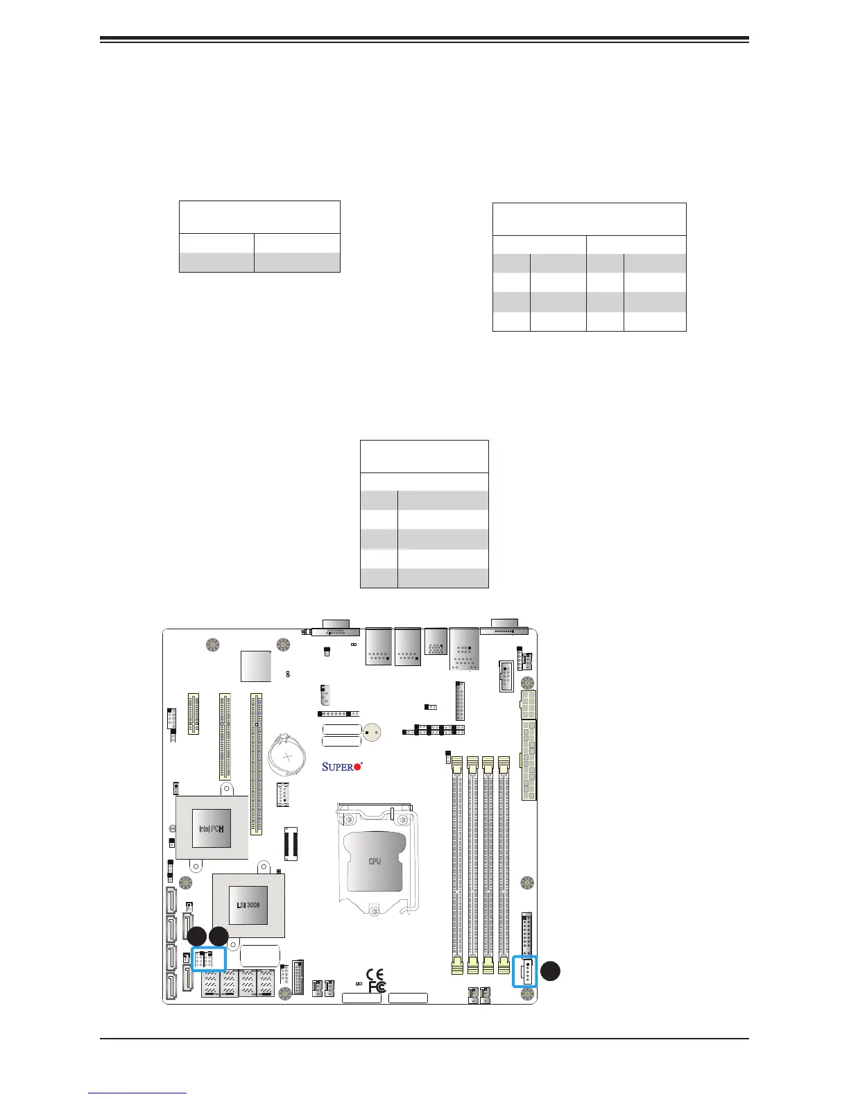
1. I-SGPIO1
2. I-SGPIO2
3. PWR SMB
SGPIO Headers
Two I-SGPIO (Serial Link General Purpose Input/Output) headers are located on the
motherboard. They support the onboard I-SATA 3.0 ports. Refer to the tables below for pin
denitions.
SGPIO Header
Pin Denitions
Pin# Denition Pin# Denition
1 NC 2 NC
3 GND 4 Data
5 Load 6 GND
7 Clock 8 NC
NC = No Connection
I-SGPIO 1/2
I-SGPIO1 Ports 2-4
I-SGPIO2 Ports 5-7
Power SMB (I
2
C) Header
The Power System Management Bus (I
2
C) connector (JPI
2
C1) monitors the power supply,
fan, and system temperatures. Refer to the table below for pin denitions.
Power SMB Header
Pin Denitions
Pin# Denition
1 Clock
2 Data
3 PMBUS_Alert
4 Ground
5 +3.3V
3

 Loading...


