43
Chapter 2: Installation
C
A
PRESS FIT
A
BAR CODE
REV:1.01
X12STL-IF
DESIGNED IN USA
BIOS LICENSE
JD1
MH4
MH2
JPL1
JL1
JPME2
I-SATA5
JSD1
I-SATA4
BT1
JSMB1
JPV1
MH1
FAN1
FAN2
JPWR1
MH3
JF1
JPI2C1
FAN3
JUIDB1
JMD1_SRW1
JTPM1
LED1
JBT1
JMD1
JPCIE1
JRF1
FANA
JPG1
JCPLD1
JVRM1
JPL2
JWD1
LED3
LED2
LEDM1
CPU
DIMMB1
CPU SLOT7 PCI-E 4.0 X16
DIMMA1
OH
NIC1
VGA
X
PWR
HDD
LED
PWR
LED
RST
FF
I-SATA0-3
LAN1/2
JF1:
NIC2
ON
USB 6/7(3.2)
USB 2/3
COM
USB 0/1
USB 4/5(3.2)
BMC_LAN
UID
JSD2
1
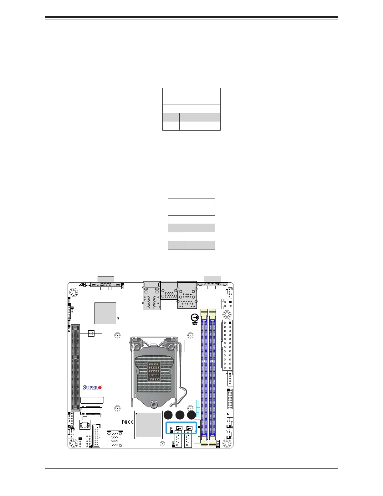
1. Chassis Intrusion
2. JSD1
3. JSD2
DOM Power
Pin Denitions
Pin# Denition
1 5V
2 Ground
3 Ground
2
Disk-On-Module Power Connector
Two power connectors for SATA DOM (Disk-On-Module) devices are located at JSD1 and
JSD2. Connect appropriate cables here to provide power support for your third party serial
DOM devices.
3
Chassis Intrusion
A Chassis Intrusion header is located at JL1 on the motherboard. Attach the appropriate cable
from the chassis to inform you of a chassis intrusion when the chassis is opened. Refer to
the table below for pin denitions.
Chassis Intrusion
Pin Denitions
Pin# Denition
1 Intrusion Input
2 Ground

 Loading...


