2-24
X9DRG-O(T)F-CPU/X9DRG-O-PCIE Platform User’s Manual
SW1
JPW10
J21
SP1
JBT1
JITP0
JSD2
JSD1
JTPM1
I_SATA1
I-SATA0
I-SATA2
I_SATA3
JF1
JWD1
JBR1
JPME1
JPL1
JPG1
J29
JPB1
J30
LE1
LE4
DM1
FAN8
FAN6
FAN7
FAN5
FAN1
FAN3
FAN4
JSPK1
JL1
JOH1
JPLD1
JPW18
JPW17
JPW6
JPW12
JPW4
JPW5
JPW3
JPW13
JPW14
JPW15
JPW16
T-SGPIO2
T-SGPIO1
T-SGPIO-S1
BT1
JPW24
JPW23
JPW22
JPW21
BIOS
LICENSE
10G MAC CODE
10G SAN MAC
1G MAC CODE
IPMI CODE
BAR CODE
P2-DIMME1
P2-DIMME2
P2-DIMME3
P2-DIMMF1
P2-DIMMF2
P2-DIMMF3
USB10/11
USB2/3
CPU1
P1-DIMMC1
P1-DIMMC2
P1-DIMMC3
P1-DIMMD1
P1-DIMMD2
P1-DIMMD3
LAN2
LAN1
CPU2
P1-DIMMB3
P1-DIMMB2
VGA1
P1-DIMMB1
P2-DIMMH3
COM1
P1-DIMMA3
P1-DIMMA2
P2-DIMMH2
P1-DIMMA1
P2-DIMMH1
IPMI_LAN
P2-DIMMG3
USB0/1
P2-DIMMG2
P2-DIMMG1
REV:1.00
X9DRG-OF-CPU
S_SATA1
FAN2
JPW7
I_SATA4
I_SATA5
S_SATA2
S_SATA2
S_SATA3
JPME2
CLOSE 1st
OPEN 1st
CLOSE 1st
OPEN 1st
USB8/9
PCH
BIOS
LAN
CTRL
BMC
BMC Firmware
CLK Chip
USB6
J34
J33
J32
J31
Power Button
Blue+ (OH/Fan Fail/
PWR FaiL/UID LED)
1
NIC1 Link LED
Reset Button
2
Power Fail LED
HDD LED
FP PWRLED
Reset
PWR
3.3 V
ID_UID_SW/3/3V Stby
Red+ (Blue LED Cathode)
Ground
Ground
1920
3.3V
X
Ground
NMI
X
NIC2 Link LED
NIC2 Activity LED
NIC1 Activity LED
B
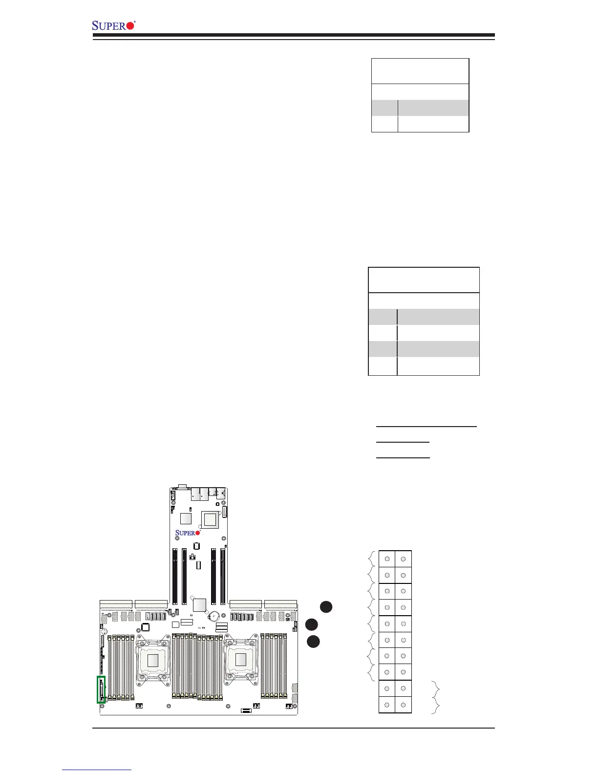
NIC1/NIC2 LED Indicators
The NIC (Network Interface Controller) LED con-
nection for LAN port 1 is located on pins 11 and
12 of JF1, and the LED connection for LAN Port 2
is located on pins 9 and 10. Attach the NIC LED
cables here to display network activity. Refer to
the table on the right for pin denitions.
C
A. HDD LED/UID Switch
B. NIC1 LED
C. NIC2 LED
A
HDD LED/UID Switch
The HDD/UID Switch connection is located on pins
13 and 14 of JF1. Attach a hard drive LED cable
here to display HDD activities, including Serial ATA
activities. Connect a UID switch cable to use UID
switch connection. The front UID switch works in
conjunction with UID LED located at pins 7/8 and
rear UID LED (LE4). Also refer to page 2-21 for
more UID switch/LED information. See the table
on the right for pin denitions.
HDD LED/UID Switch
Pin Denitions (JF1)
Pin# Denition
13 UID Switch/3,3V
14 HDD Active
GLAN1/2 LED
Pin Denitions (JF1)
Pin# Denition
9 NIC 2 Act. LED
10 NIC 2 Link LED
11 NIC 1 Act. LED
12 NIC 1 Link LED

 Loading...


