SW1
JPW10
J21
SP1
JBT1
JITP0
JSD2
JSD1
JTPM1
I_SATA1
I-SATA0
I-SATA2
I_SATA3
JF1
JWD1
JBR1
JPME1
JPL1
JPG1
J29
JPB1
J30
LE1
LE4
DM1
FAN8
FAN6
FAN7
FAN5
FAN1
FAN3
FAN4
JSPK1
JL1
JOH1
JPLD1
JPW18
JPW17
JPW6
JPW12
JPW4
JPW5
JPW3
JPW13
JPW14
JPW15
JPW16
T-SGPIO2
T-SGPIO1
T-SGPIO-S1
BT1
JPW24
JPW23
JPW22
JPW21
BIOS
LICENSE
10G MAC CODE
10G SAN MAC
1G MAC CODE
IPMI CODE
BAR CODE
P2-DIMME1
P2-DIMME2
P2-DIMME3
P2-DIMMF1
P2-DIMMF2
P2-DIMMF3
USB10/11
USB2/3
CPU1
P1-DIMMC1
P1-DIMMC2
P1-DIMMC3
P1-DIMMD1
P1-DIMMD2
P1-DIMMD3
LAN2
LAN1
CPU2
P1-DIMMB3
P1-DIMMB2
VGA1
P1-DIMMB1
P2-DIMMH3
COM1
P1-DIMMA3
P1-DIMMA2
P2-DIMMH2
P1-DIMMA1
P2-DIMMH1
IPMI_LAN
P2-DIMMG3
USB0/1
P2-DIMMG2
P2-DIMMG1
REV:1.00
X9DRG-OF-CPU
S_SATA1
FAN2
JPW7
I_SATA4
I_SATA5
S_SATA2
S_SATA2
S_SATA3
JPME2
CLOSE 1st
OPEN 1st
CLOSE 1st
OPEN 1st
USB8/9
PCH
BIOS
LAN
CTRL
BMC
BMC Firmware
CLK Chip
USB6
J34
J33
J32
J31
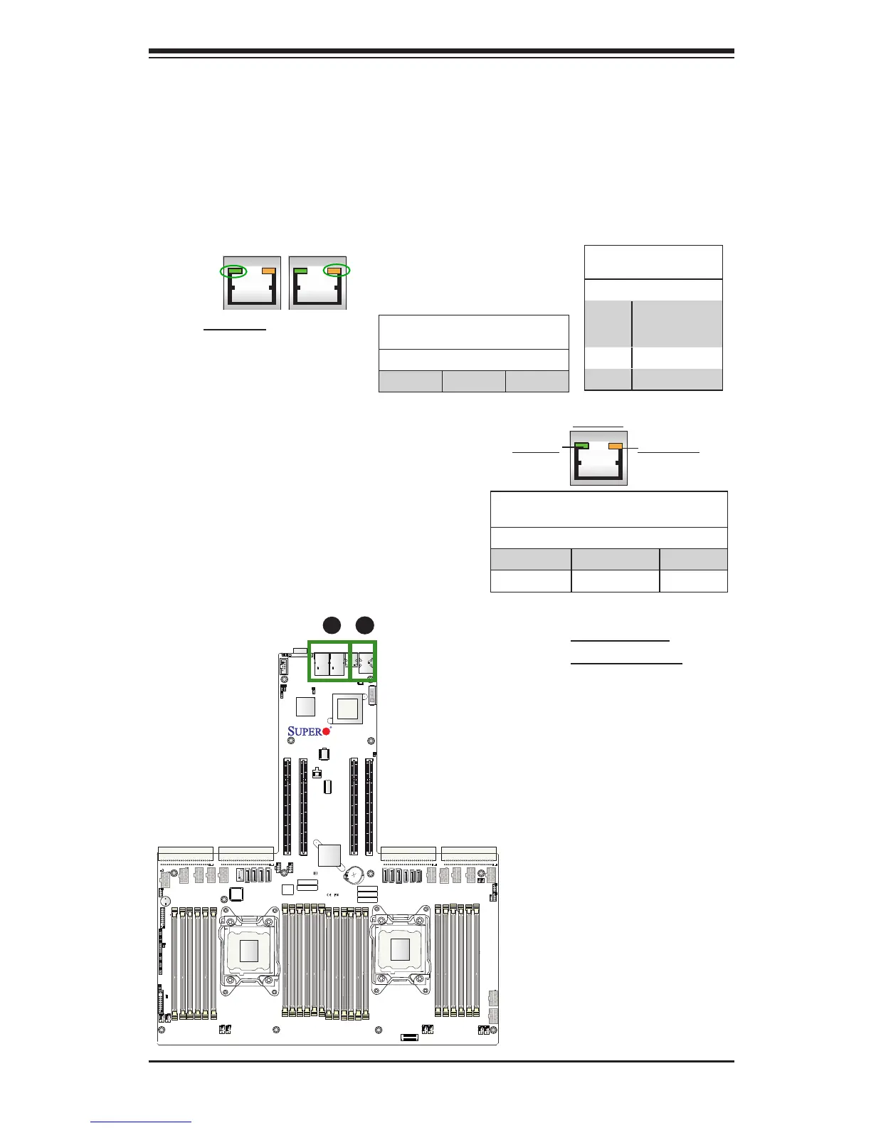
2-9 Onboard LED Indicators
A. LAN1/2 LEDs
B. IPMI LAN LEDs
IPMI Dedicated LAN LEDs
In addition to LAN 1/LAN 2, an IPMI Dedicated
LAN is also located on the I/O Backplane of
the motherboard. The amber LED on the
right indicates activity, while the green LED
on the left indicates the speed of the con-
nection. See the table on the right for more
information.
Link LED Activity LED
IPMI LAN
IPMI LAN Link LED (Left) &
Activity LED (Right)
Color/State Denition
Link (Left) Green: Solid 100 Mbps
Activity (Right) Amber: Blinking Active
LAN LEDs
There are two LAN ports on the motherboard. Each Ethernet LAN port has two
LEDs. The Yellow LED on the right indicates activity. The LED on the left is the Link
LED, which can be green, amber or off to indicate the speed of the connection. See
the tables below for more information.
Activity LED
Link LED
GLAN/10G LAN (TLAN) Activity
LED Settings (Right)
Color Status Denition
Green Flashing Active
Rear View (when facing the
rear side of the chassis)
A
B
LAN 1/LAN 2 Link LED
(Left) LED State
LED Color Denition
Off 10 Mbps, 100
Mbps, or No
Connection
Amber 1 Gbps
Green 10 Gbps

 Loading...


