2-22
10SLM-F/X10SLL-F/X10SLL-SF/X10SLL-S User’s Manual
Power Button
OH/Fan Fail
1
NIC1 Activity LED
Reset Button
2
Power Fail LED
HDD LED
FP PWRLED
Reset
PWR
3.3 V
UID Switch
Blue LED
Ground
Ground
1920
3.3V
X
Ground
NMI
X
NIC2 Activity LED
3.3V Stby
3.3V Stby
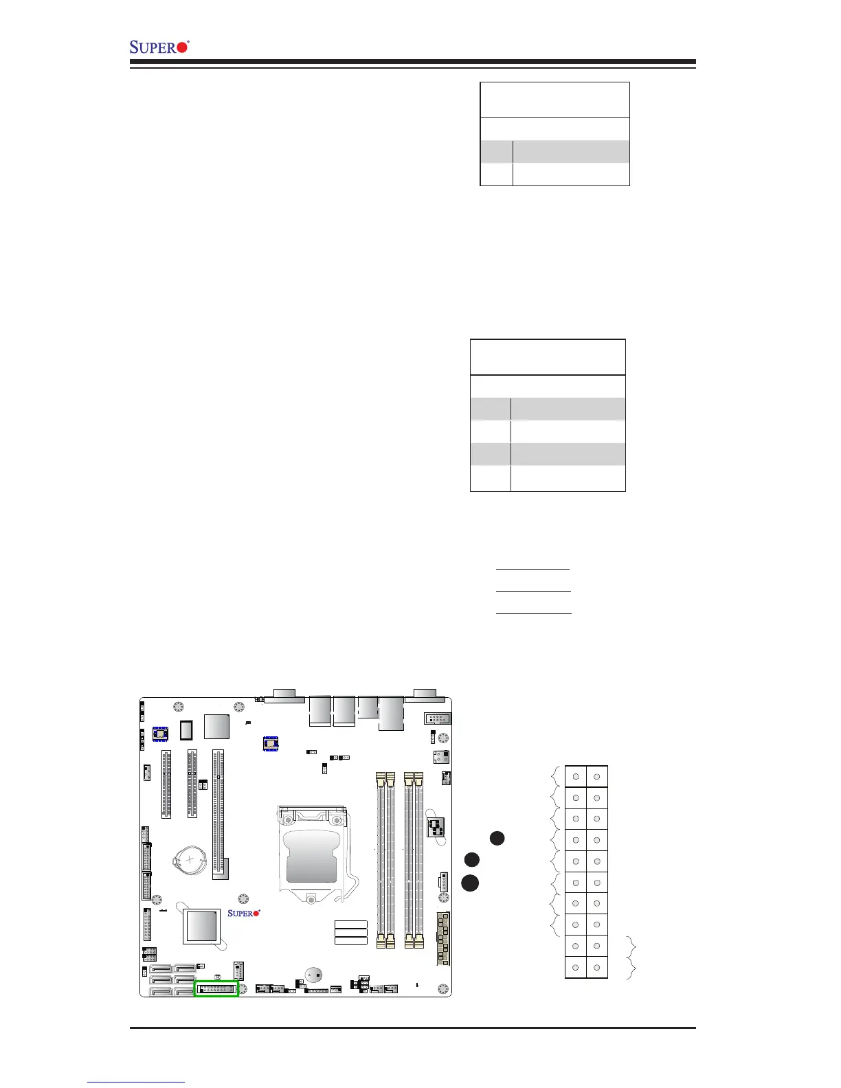
A. HDD LED
B. NIC1 LED
C. NIC2 LED
A
B
HDD LED
The HDD LED connection is located
on pins 13 and 14 of JF1. Attach a
cable here to indicate HDD activ-
ity. See the table on the right for pin
denitions.
HDD LED
Pin Denitions (JF1)
Pin# Denition
13 3.3V Stby/UID_SW
14 HD Active
NIC1/NIC2
The NIC (Network Interface Control-
ler) LED connection for LAN Port 1
is located on pins 11 and 12 of JF1,
and the LED connection for LAN Port
2 is on Pins 9 and 10. Attach the NIC
LED cables to the LED indicators
mentioned above to display network
activity. Refer to the layout below for
the locations of NIC LED indicators.
LAN1/2 LED
Pin Denitions (JF1)
Pin# Denition
9 3.3V Stby
10 NIC 2 Activity LED
11 3.3V Stby
12 NIC 1 Activity LED
C

 Loading...