2-36
10SLM-F/X10SLL-F/X10SLL-SF/X10SLL-S User’s Manual
FAN2
JP9
SW1
T-SGPIO1
JSTBY1
JIPMB1
JPW2
JSD1
LED3
LED2
JD1
LED5
LED1
JPI2C1
BT1
JPW1
JTPM1
FANA
FAN3
FAN1
FAN2
FAN4
JPL1
JPL2
JPME2
JWD1
JPG1
JBR1
JPME1
J19
J18
J7
JVR1
JI2C1
JI2C2
JOH1
JP8
JL1
JP2
JP1
JP7
USB 3.0-0
USB 3.0-1
USB 3.0-2/3
VGA
LAN2
LAN1
USB4/5
USB6/7
IPMI_LAN
COM2
COM1
P1-DIMMB1
P1-DIMMB2
P1-DIMMA2
P1-DIMMA1
PCH SLOT4 PCI-E 2.0 X4(IN X8)
CPU SLOT5 PCI-E 3.0 X8
CPU SLOT6 PCI-E 3.0 X8(IN X16)
JF1
I-SATA4
I-SATA3
I-SATA5 I-SATA2
I-SATA1
I-SATA0
USB8/9
JRK1
T-SGPIO2
JPB1
X10SLM-F/X10SLL(-F/SF/S)
Rev. 1.02
BMC FW
FP Control
PCH
BMC
CTRL
CPU
SP1
LED4
IPMI Code
BAR Code
MAC Code
JBT1
BIOS
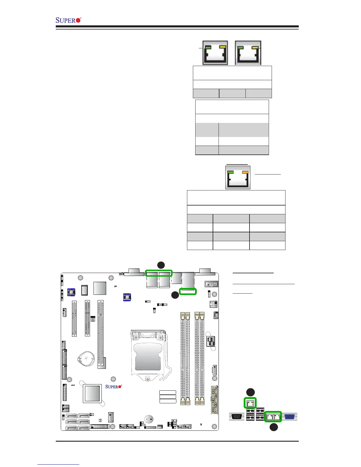
A. LAN1/2 LEDs
B. IPMI_LAN LED (for -F
models)
A
B
LAN1/LAN2 LEDs
Two LAN ports (LAN1/LAN2) are
located on the I/O backplane of the
motherboard. Each Ethernet LAN port
has two LEDs. The yellow LED indi-
cates activity, while the Link LED may
be green, amber, or off to indicate the
speed of the connections. See the
tables at right for more information.
2-9 Onboard Indicators
Activity LED
B
Link LED
GLAN Ports 1/2 Link Indicator
LED Settings
LED Color Denition
Off No Connection/10
Mbps
Amber 1 Gbps
Green 100 Mbps
GLAN 1/2 Activity Indicator
LED Settings
Color Status Denition
Yellow Flashing Active
A
IPMI_Dedicated LAN LEDs (For F
Models)
An IPMI_Dedicated LAN is also lo-
cated on the I/O Backplane of the F
model boards. The amber LED on
the right indicates connection and
activity, while the green LED on the
left indicates the speed of the con-
nection. See the table on the right.
Activity LED
IPMI LAN
IPMI LAN Link Speed LED (Left) &
Connection Activity LED (Right)
LED Color/State Denition
Off Off No Connection
Activity Amber: Blinking Active
Speed Green: Solid 100 Mbps
Speed Amber: Solid 1 Gbps
Link Speed LED
 Loading...


