Video Connection
A Video (VGA) port is located next
to LAN2 on the I/O backplane. Refer
to the board layout below for the
location.
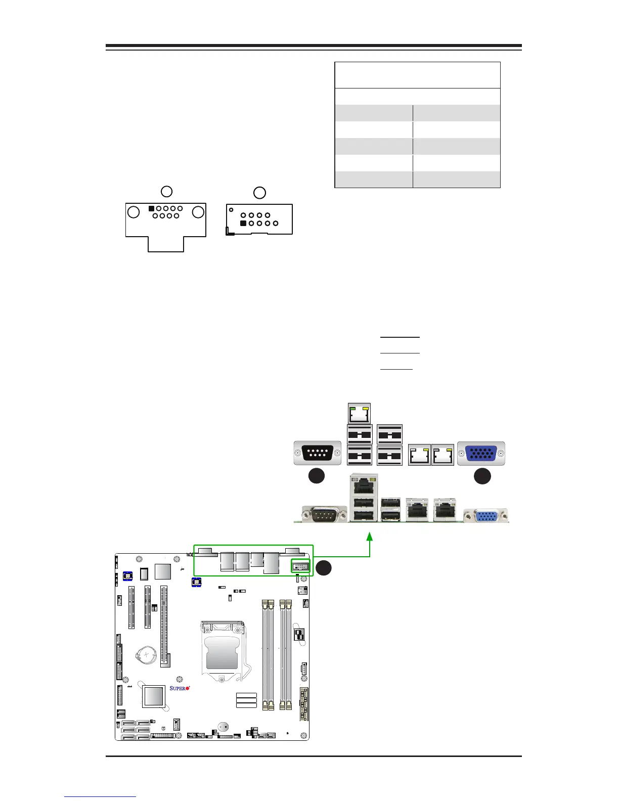
Serial Ports
Two COM connections (COM1 &
COM2) are located on the mother-
board. COM1 is located on the Back-
plane I/O panel. COM2 is located next
to COM1. See the table on the right for
pin denitions.
Serial COM) Ports
Pin Denitions
Pin # Denition Pin # Denition
1 DCD 6 DSR
2 RXD 7 RTS
3 TXD 8 CTS
4 DTR 9 RI
5 Ground 10 N/A
 Loading...


