2-22
X8DAL-3/X8DAL-i User's Manual
COM1
JC1
CD1
JPI2C
SAS7
JPS1
JPL1
JPL2
JPUSB1
JPUSB2
JF1
FAN5
FAN6
FAN1
1
T-SGPIO2
T-SGPIO1
Battery
JL1
1
JD1
1
1
JI2C2
JI2C1
USB 0/1/2/3
Slot4 PCI 33MHz
JBT1
Slot6 PCI-E 2.0x16
Slot3 PCI-E 2.0x4 (in x16 Slot)
Slot2 PCI-E x4(in x 8 Slot)
ICH10R
5500
LES2
P2-DIMM3A
P2-DIMM1A
P1-DIMM3A
P2-DIMM2A
P1-DIMM2A
P1-DIMM1A
KB/Mouse
LAN2
LAN1
Slot5 PCI 33MHz
JPAC
USB8/9
USB6/7
3-SGPIO2
3-SGPIO1
JPW3
JPW1
JPW2
FAN4
FAN3
LAN
CTRL
LAN
CTRL
Audio
BIOS
SAS6
SAS5
SAS4
SAS3
SAS2
SAS1
SAS0
I-SATA0
I-SATA1
I-SATA2
I-SATA3
I-SATA4
I-SATA5
LE1
JWD
SP1
SPKR
LSI 1068
SAS CTRL
Intel
Intel
SIO
Audio
CTRL
HW
Monitor
X8DAL-3/i Rev.1.01
FP CTRL
JOH1
FP Audio
COM2
FAN2
IOH-24D
South Bridge
JP5
LES1
2-6 Connecting Cables
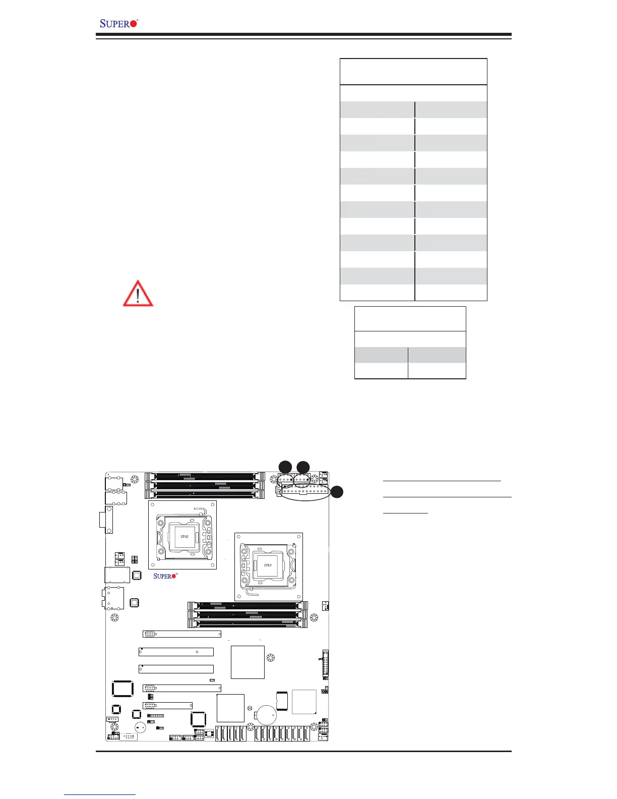
Power Connectors
A 24-pin main power supply connector(JPW1)
and two 8-pin CPU PWR connectors (JPW2/
JPW3) on the motherboard. These power
connectors meet the SSI EPS 12V specifi -
cation. In addition to the 24-pin ATX power
connector, the 12V 8-pin CPU PWR connec-
tors at JPW2/JPW3 must also be connected
to your power supply. See the table on the
right for pin defi nitions.
ATX Power 24-pin Connector
Pin Defi nitions
Pin# Defi nition Pin # Defi nition
13 +3.3V 1 +3.3V
14 -12V 2 +3.3V
15 COM 3 COM
16 PS_ON 4 +5V
17 COM 5 COM
18 COM 6 +5V
19 COM 7 COM
20 Res (NC) 8 PWR_OK
21 +5V 9 5VSB
22 +5V 10 +12V
23 +5V 11 +12V
24 COM 12 +3.3V
12V 8-pin PWR Connector
Pin Defi nitions
Pins Defi nition
1 through 4 Ground
5 through 8 +12V
A. 24-pin ATX PWR (Req'd)
B/C.8-pin Processor PWR
(Required)
A
B
C
Warning: To prevent damage to
the power supply or motherboard,
please use a power supply that
contains a 24-pin and two 8-pin
power connectors. Be sure to
connect these connectors to the
24-pin (JPW1) and the two 8-pin
(JPW2,JPW3) power connectors
on the motherboard. Failure in do-
ing so will void the manufacturer
warranty on your power supply and
motherboard.
(Required)
 Loading...