Chapter 2: Installation
2-27
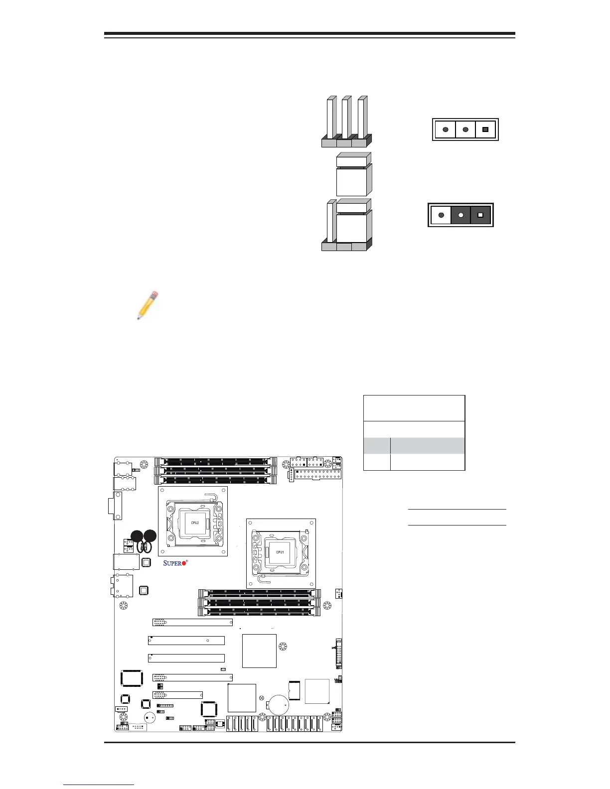
COM1
JC1
CD1
JPI2C
SAS7
JPS1
JPL1
JPL2
JPUSB1
JPUSB2
JF1
FAN5
FAN6
FAN1
1
T-SGPIO2
T-SGPIO1
Battery
JL1
1
JD1
1
1
JI2C2
JI2C1
USB 0/1/2/3
Slot4 PCI 33MHz
JBT1
Slot6 PCI-E 2.0x16
Slot3 PCI-E 2.0x4 (in x16 Slot)
Slot2 PCI-E x4(in x 8 Slot)
ICH10R
5500
LES2
P2-DIMM3A
P2-DIMM1A
P1-DIMM3A
P2-DIMM2A
P1-DIMM2A
P1-DIMM1A
KB/Mouse
LAN2
LAN1
Slot5 PCI 33MHz
JPAC
USB8/9
USB6/7
3-SGPIO2
3-SGPIO1
JPW3
JPW1
JPW2
FAN4
FAN3
LAN
CTRL
LAN
CTRL
Audio
BIOS
SAS6
SAS5
SAS4
SAS3
SAS2
SAS1
SAS0
I-SATA0
I-SATA1
I-SATA2
I-SATA3
I-SATA4
I-SATA5
LE1
JWD
SP1
SPKR
LSI 1068
SAS CTRL
Intel
Intel
SIO
Audio
CTRL
HW
Monitor
X8DAL-3/i Rev.1.01
FP CTRL
JOH1
FP Audio
COM2
FAN2
IOH-24D
South Bridge
JP5
LES1
2-7 Jumper Settings
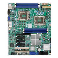
Explanation of Jumpers
To modify the operation of the mother-
board, jumpers can be used to choose
between optional settings. Jumpers cre-
ate shorts between two pins to change
the function of the connector. Pin 1
is identifi ed with a square solder pad
on the printed circuit board. See the
motherboard layout pages for jumper
locations.
Note: On two pin jumpers,
"Closed" means the jumper
is on and "Open" means the
jumper is off the pins.
Connector
Pins
Jumper
Cap
Setting
Pin 1-2 short
3 2 1
3 2 1
GLAN Enable/Disable
JPL1/JPL2 enable or disable the GLAN
Port1/GLAN Port2 on the mother-
board. See the table on the right for
jumper settings. The default setting is
Enabled.
GLAN Enable
Jumper Settings
Pin# Defi nition
1-2 Enabled (default)
2-3 Disabled
A
A. GLAN Port 1 Enable
B. GLAN Port 2 Enable
B
 Loading...