2-30
X8DAL-3/X8DAL-i User's Manual
COM1
JC1
CD1
JPI2C
SAS7
JPS1
JPL1
JPL2
JPUSB1
JPUSB2
JF1
FAN5
FAN6
FAN1
1
T-SGPIO2
T-SGPIO1
Battery
JL1
1
JD1
1
1
JI2C2
JI2C1
USB 0/1/2/3
Slot4 PCI 33MHz
JBT1
Slot6 PCI-E 2.0x16
Slot3 PCI-E 2.0x4 (in x16 Slot)
Slot2 PCI-E x4(in x 8 Slot)
ICH10R
5500
LES2
P2-DIMM3A
P2-DIMM1A
P1-DIMM3A
P2-DIMM2A
P1-DIMM2A
P1-DIMM1A
KB/Mouse
LAN2
LAN1
Slot5 PCI 33MHz
JPAC
USB8/9
USB6/7
3-SGPIO2
3-SGPIO1
JPW3
JPW1
JPW2
FAN4
FAN3
LAN
CTRL
LAN
CTRL
Audio
BIOS
SAS6
SAS5
SAS4
SAS3
SAS2
SAS1
SAS0
I-SATA0
I-SATA1
I-SATA2
I-SATA3
I-SATA4
I-SATA5
LE1
JWD
SP1
SPKR
LSI 1068
SAS CTRL
Intel
Intel
SIO
Audio
CTRL
HW
Monitor
X8DAL-3/i Rev.1.01
FP CTRL
JOH1
FP Audio
COM2
FAN2
IOH-24D
South Bridge
JP5
LES1
A
A. SAS Enable
B. Backplane USB Wake-
UP Enable
B. Front Panel USB Wake-
UP Enable
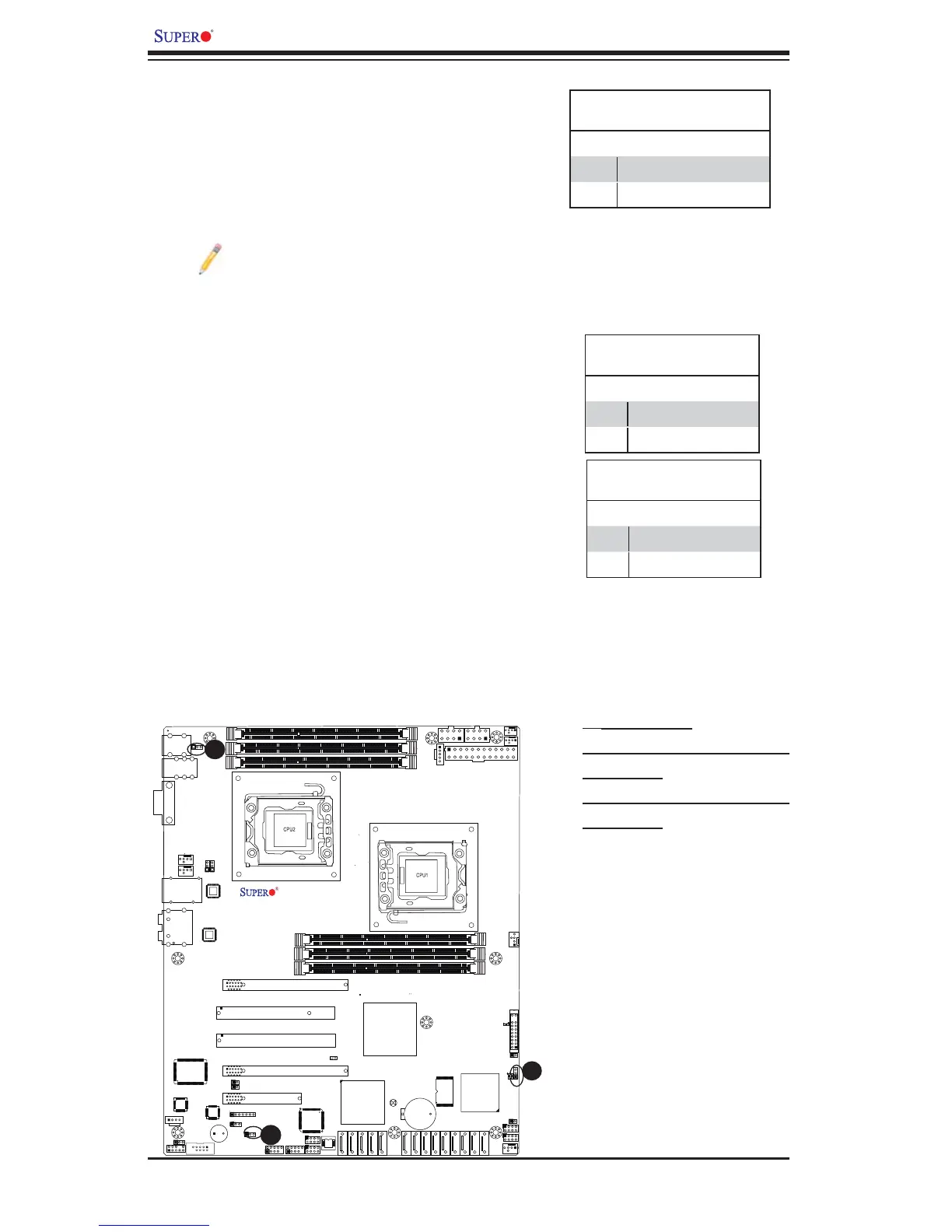
SAS Enable/Disable (X8DAL-3 only)
Jumper JPS1 allows you to enable or disable the
onboard SAS connections. The default setting is
Pins 1-2 to enable the connection. See the table
on the right for jumper settings.
SAS Enable
Jumper Settings
Jumper Setting Defi nition
1-2 SAS Enabled (Default)
2-3 SAS Disabled
Note: For more information on LSI SAS RAID please refer to the LSI Mega-
RAID User's Guide @ http://www.supermicro.com/support/manuals/.
USB Wake-Up
The system may be woken up from the standby
state by pushing a key on a USB keyboard con-
nected to an enabled USB port. JPUSB1 is for the
rear I/O USB ports and JPUSB2 is for the front
access USB headers. See the tables on the right
for jumper settings.
JPUSB1 (BackPanel USB
Wake-up Enable)
Pin# Defi nition
1-2 Enabled (Default)
2-3 Disabled
JPUSB2 (Front Panel USB
Wake-up Enable)
Pin# Defi nition
1-2 Enabled
2-3 Disabled (Default)
B
C
 Loading...