Chapter 2: Installation
2-23
COM1
JC1
CD1
JPI2C
SAS7
JPS1
JPL1
JPL2
JPUSB1
JPUSB2
JF1
FAN5
FAN6
FAN1
1
T-SGPIO2
T-SGPIO1
Battery
JL1
1
JD1
1
1
JI2C2
JI2C1
USB 0/1/2/3
Slot4 PCI 33MHz
JBT1
Slot6 PCI-E 2.0x16
Slot3 PCI-E 2.0x4 (in x16 Slot)
Slot2 PCI-E x4(in x 8 Slot)
ICH10R
5500
LES2
P2-DIMM3A
P2-DIMM1A
P1-DIMM3A
P2-DIMM2A
P1-DIMM2A
P1-DIMM1A
KB/Mouse
LAN2
LAN1
Slot5 PCI 33MHz
JPAC
USB8/9
USB6/7
3-SGPIO2
3-SGPIO1
JPW3
JPW1
JPW2
FAN4
FAN3
LAN
CTRL
LAN
CTRL
Audio
BIOS
SAS6
SAS5
SAS4
SAS3
SAS2
SAS1
SAS0
I-SATA0
I-SATA1
I-SATA2
I-SATA3
I-SATA4
I-SATA5
LE1
JWD
SP1
SPKR
LSI 1068
SAS CTRL
Intel
Intel
SIO
Audio
CTRL
HW
Monitor
X8DAL-3/i Rev.1.01
FP CTRL
JOH1
FP Audio
COM2
FAN2
IOH-24D
South Bridge
JP5
LES1
Chassis Intrusion
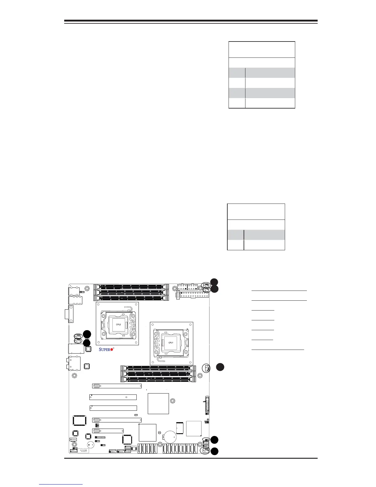
A Chassis Intrusion header is located
at JL1 on the motherboard. Attach an
appropriate cable from the chassis to
inform you of a chassis intrusion when
the chassis is opened.
Chassis Intrusion
Pin Defi nitions (JL1)
Pin# Defi nition
1 Intrusion Input
2 Ground
C
A. Fan 1 (CPU2 Fan)
B. Fan 2 (CPU1 Fan)
C. Fan 3
D. Fan 4
E. Fan 5
F. Fan 6
G. Chassis Intrusion
Fan Headers
This motherboard has four chassis/
system fan headers (Fan 3 to Fan6) and
two CPU fans (Fan1/Fan2) on the moth-
erboard. All these 4-pin fans headers are
backward compatible with the traditional
3-pin fans. However, fan speed control
is available for 4-pin fans only. The fan
speeds are controlled by Thermal Man-
agement via Hardware Monitoring in
the Advanced Setting in the BIOS. (The
Default setting is Disabled.) See the table
on the right for pin defi nitions.
Fan Header
Pin Defi nitions
Pin# Defi nition
1 Ground
2 +12V
3 Tachometer
4 PWR Modulation
A
B
 Loading...