Chapter 2: Installation
2-25
J5
T-SGPIO2
T-SGPIO1
JLAN2
JLAN1
JF1
1
COM2
JWOL
Battery
JSM1
JSM2
JBT1
JUSB2
JUSB3
1
BMC/VGA
CTRL
J26
JPG1
JPL1
JPL2
JWD
JPS1
JPT1
JI2C2
JI2C1
D1
LE1
LES2
J6
JD1
SP1
JOH1
JL1
JPS2
JPW3
JPW1
JPW2
1
X8DT3/i Series
BIOS
LAN3
LAN1
LAN2
VGA
Slot6 PCI-E 2.0x8
PCI 33 MHz
I-BUTTON
P1-DIMM3A
P1-DIMM3B
P1-DIMM2A
P1-DIMM2B
P1-DIMM1A
P1-DIMM1B
P2-DIMM1A
P2-DIMM2B
P2-DIMM2A
P2-DIMM3B
SAS4~7
SAS0~3
Fan6
Fan5
Fan2
Fan8/
CPU2 FAN
Fan4
Fan3
Fan7/
CPU1
Fan1
Slot3
P2-DIMM3A
KB/MOUSE
COM1
LAN4
Slot2 PCI-E x4
I-SATA0
I-SATA1
I-SATA2
I-SATA3
I-SATA4
Slot1 PCI 33MHz
Floppy
USB6/7
USB4/5
USB3
USB2
USB 0/1
I-SATA5
P2-DIMM1B
LAN
CTRL
LAN
CTRL
Slot5 PCI-E 2.0x8 in x16
CPU2
CPU1
ICH10R
North Bridge
LSI
1068E
LES1
(X8DT3/i-LN4F)
SI/O
(*X8DT3 Models only)
SPEC
Dedicated LAN
Slot4 PCI-E 2.0 x16
(X8DT3/i-F/-LN4F only)
(*X8DT3 Models only)
J27J28
JPB
Intel 5520
South Bridge
A
B
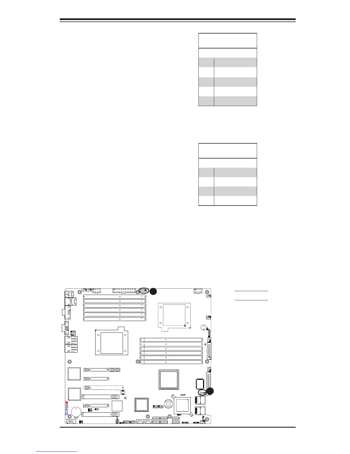
A. PWR SMB
B. IPMB SMB
IPMB I
2
C SMB
A System Management Bus header
for the IPMI slot is located at J5.
Connect the appropriate cable here
to use the IPMB I
2
C connection on
your system.
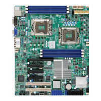
SMB Header
Pin Defi nitions
Pin# Defi nition
1 Data
2 Ground
3 Clock
4 No Connection
Power SMB (I
2
C) Connector
Power System Management Bus
(I
2
C) Connector (J6) monitors power
supply, fan and system temperatures.
See the table on the right for pin
defi nitions.
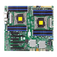
PWR SMB
Pin Defi nitions
Pin# Defi nition
1 Clock
2 Data
3 PWR Fail
4 Ground
5 +3.3V
 Loading...