Chapter 2: Installation
2-11
JPW3
JPW2
JBT1
JPI2C
COM1
I-SATA0
I-Button
JPS1
JWD
JPL2
JPL1
JF1
SP1
1
JWOL
LE1
D20
JBAT1
JP3
JL1
JPS2
JOH1
JPB
JP5
J16
JD1
CPU1 FAN
Slot3 PCI-E 1.0 x4
7HG
5ADG
7TN100C
W8379
W8352
Slot6 PCI-E 2.0 x8 (in x16 Slot)
JI2C2
SAS6
SAS5
SAS4
SAS3
SAS2
SAS1
Slot4 PCI-E 2.0 x8
BMC CTRL
WPCM450-R
LC4128ZE-
ICH10R
(South Bridge)
5500
(North Bridge)
LES2
P1-DIMM3A
P1-DIMM1A
P2-DIMM3A
P1-DIMM2A
P2-DIMM2A
P2-DIMM1A
KB/Mouse
USB0/1
VGA
LAN1
UID
LE2
Slot2 PCI 33MHz
Slot1 PCI 33MHz
COM2
IPMB
USB4/5
USB6
T-SGPIO2
USB2/3
I-SATA5
T-SGPIO1
I-SATA3
I-SATA2
I-S ATA4
I-SATA1
3-SGPIO2
3-SGPIO1
LSI SAS1068E
SAS0
FAN5
FAN4
FAN6
FAN1/
CPU2
LAN2
IPMI LAN
LAN
CTRL
SAS7
JI2C1
LAN
CTRL
PHY
Chip
CPU1
Intel
Intel
JPW1
CPU2FAN
FAN2/
BIOS
Slot5 PCI-E 2.0 x4 (in x8 Slot)
X8DTL Series
Flash ROM
BMC
Battery
Buzzer
1
FAN3
JPG1
(in x8 Slot)
Rev. 2.01
JWOR
JWF1
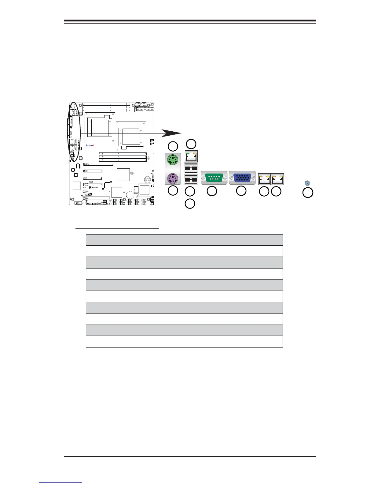
2-5 Control Panel Connectors/IO Ports
The I/O ports are color coded in conformance with the PC 99 specifi cation. See
the picture below for the colors and locations of the various I/O ports.
1. Back Panel Connectors/IO Ports
Back Panel I/O Port Locations and Defi nitions
Back Panel Connectors
Keyboard (Purple)1.
PS/2 Mouse (Green)2.
Back Panel USB Port 03.
Back Panel USB Port 14.
Dedicated LAN (X8DTL-3F/iF only)5.
COM Port 1 (Turquoise)6.
VGA (Blue) 7.
Gigabit LAN 18.
Gigabit LAN 29.
UID Switch10.
10
 Loading...