2-24
X8DTL-3/X8DTL-i/X8DTL-3F/X8DTL-iF User's Manual
JPW3
JPW2
JBT1
JPI2C
COM1
I-SATA0
I-Button
JPS1
JWD
JPL2
JPL1
JF1
SP1
1
JWOL
LE1
D20
JBAT1
JP3
JL1
JPS2
JOH1
JPB
JP5
J16
JD1
CPU1 FAN
Slot3 PCI-E 1.0 x4
7HG
5ADG
7TN100C
W8379
W8352
Slot6 PCI-E 2.0 x8 (in x16 Slot)
JI2C2
SAS6
SAS5
SAS4
SAS3
SAS2
SAS1
Slot4 PCI-E 2.0 x8
BMC CTRL
WPCM450-R
LC4128ZE-
ICH10R
(South Bridge)
5500
(North Bridge)
LES2
P1-DIMM3A
P1-DIMM1A
P2-DIMM3A
P1-DIMM2A
P2-DIMM2A
P2-DIMM1A
KB/Mouse
USB0/1
VGA
LAN1
UID
LE2
Slot2 PCI 33MHz
Slot1 PCI 33MHz
COM2
IPMB
USB4/5
USB6
T-SGPIO2
USB2/3
I-SATA5
T-SGPIO1
I-SATA3
I-SATA2
I-SATA4
I-SATA1
3-SGPIO2
3-SGPIO1
LSI SAS1068E
SAS0
FAN5
FAN4
FAN6
FAN1/
CPU2
LAN2
IPMI LAN
LAN
CTRL
SAS7
JI2C1
LAN
CTRL
PHY
Chip
CPU1
Intel
Intel
JPW1
CPU2FAN
FAN2/
BIOS
Slot5 PCI-E 2.0 x4 (in x8 Slot)
X8DTL Series
Flash ROM
BMC
Battery
Buzzer
1
FAN3
JPG1
(in x8 Slot)
Rev. 2.01
JWOR
JWF1
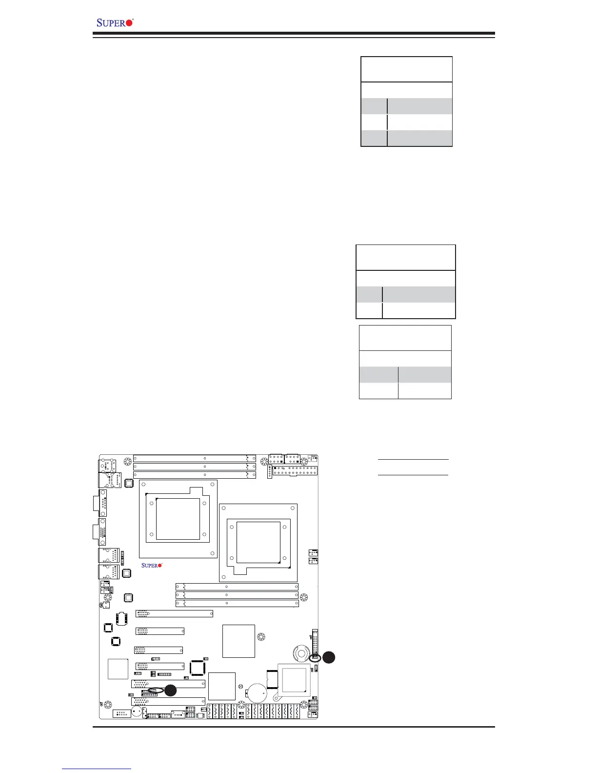
Wake-On-LAN
The Wake-On-LAN header is located at
JWOL on the motherboard. You must also
have a LAN card with a Wake-On-LAN con-
nector and a cable to use this feature. See
the table on the right for pin defi nitions.
Wake-On-LAN
Pin Defi nitions
Pin# Defi nition
1 +5V Standby
2 Ground
3 Wake-up
A
B
A. Wake-On-LAN
B. Overheat LED
Overheat LED/Fan Fail (JOH1)
The JOH1 header is used to connect an
LED indicator to provide warnings of chassis
overheating or fan failure. This LED will blink
when a fan failure occurs. Refer to the table
on right for pin defi nitions.
Overheat LED
Pin Defi nitions
Pin# Defi nition
1 5vDC
2 OH Active
OH/Fan Fail LED
Pin Defi nitions
State Message
Solid Overheat
Blinking Fan Fail
 Loading...