Chapter 2: Installation
2-23
JPW3
JPW2
JBT1
JPI2C
COM1
I-SATA0
I-Button
JPS1
JWD
JPL2
JPL1
JF1
SP1
1
JWOL
LE1
D20
JBAT1
JP3
JL1
JPS2
JOH1
JPB
JP5
J16
JD1
CPU1 FAN
Slot3 PCI-E 1.0 x4
7HG
5ADG
7TN100C
W8379
W8352
Slot6 PCI-E 2.0 x8 (in x16 Slot)
JI2C2
SAS6
SAS5
SAS4
SAS3
SAS2
SAS1
Slot4 PCI-E 2.0 x8
BMC CTRL
WPCM450-R
LC4128ZE-
ICH10R
(South Bridge)
5500
(North Bridge)
LES2
P1-DIMM3A
P1-DIMM1A
P2-DIMM3A
P1-DIMM2A
P2-DIMM2A
P2-DIMM1A
KB/Mouse
USB0/1
VGA
LAN1
UID
LE2
Slot2 PCI 33MHz
Slot1 PCI 33MHz
COM2
IPMB
USB4/5
USB6
T-SGPIO2
USB2/3
I-SATA5
T-SGPIO1
I-SATA3
I-SATA2
I-SATA4
I-SATA1
3-SGPIO2
3-SGPIO1
LSI SAS1068E
SAS0
FAN5
FAN4
FAN6
FAN1/
CPU2
LAN2
IPMI LAN
LAN
CTRL
SAS7
JI2C1
LAN
CTRL
PHY
Chip
CPU1
Intel
Intel
JPW1
CPU2FAN
FAN2/
BIOS
Slot5 PCI-E 2.0 x4 (in x8 Slot)
X8DTL Series
Flash ROM
BMC
Battery
Buzzer
1
FAN3
JPG1
(in x8 Slot)
Rev. 2.01
JWOR
JWF1
B
A
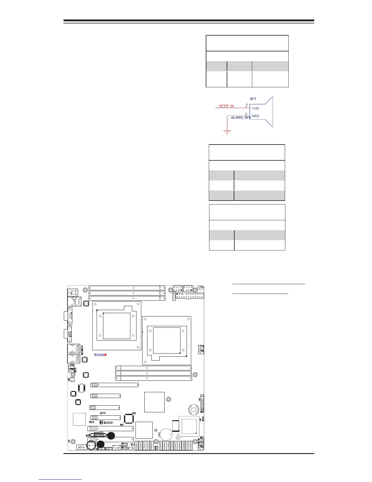
A. Internal Speaker (Buzzer)
B. PWR LED/Speaker
Power LED/Speaker
On the JD1 header, pins 1-3 are used
for power LED indication, and pins 4-7
are for the speaker. See the tables
on the right for pin defi nitions. Please
note that the speaker connector pins
(4-7) are for use with an external
speaker. If you wish to use the on-
board speaker, you should close pins
6-7 with a jumper.
Speaker Connector
Pin Defi nitions
Pin Setting Defi nition
Pins 4-7 External Speaker
Pins 6-7 Internal Speaker
Internal Speaker
The Internal Speaker, located at SP1,
can be used to provide audible indica-
tions for various beep codes. See the
table on the right for pin defi nitions.
Refer to the layout below for the loca-
tions of the Internal Buzzer (SP1).
Internal Buzzer (SP1)
Pin Defi nition
Pin# Defi nitions
Pin 1 Pos. (+) Beep In
Pin 2 Neg. (-) Alarm
Speaker
PWR LED Connector
Pin Defi nitions
Pin Setting Defi nition
Pin 1 Anode (+)
Pin2 Cathode (-)
Pin3 NA
 Loading...