2-16
X9SCM-IIF/X9SCL-IIF Series User's Manual
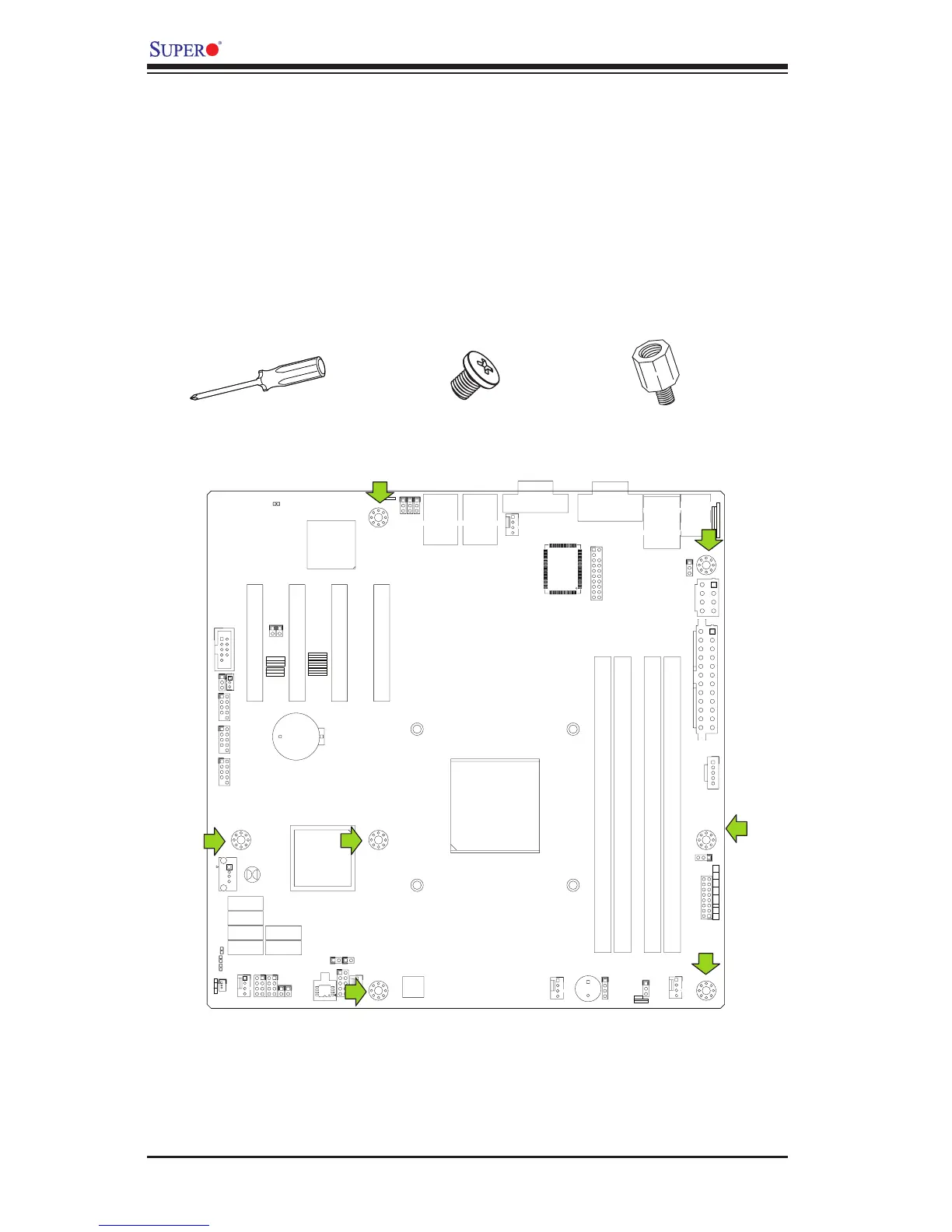
Location of Mounting Holes
1
1
JI2C2
JI2C1
SLOT4 PCI-E 2.0 X4 ON X8
U3
U4
JS2
JS1
J31
JTPM
JPME2
JPME1
J29
JL1
T-SGPIO2
T-SGPIO1
JWF1
JPW2
JWOL
J12
JSPK
JPI2C
JF1
JPW1
B1
JS6
JS3JS4
JS5
J24
JLAN2
JLAN1
COM1
SPKR1
LE3
LE4
LE2
JWD
JLED
JPL2
JPG1
JPBJPL1
JPUSB1
FANA
FAN1
FAN4
FAN3
FAN2
U82
DIMM2
DIMM3
DIMM1
DIMM4
LE7
FF
DDR3 1066/1333 UDIMM required
GND
GND
5V
1-2:RST
2-3:NMI
JWD
USB4/5
USB 12/13
_LAN
IPMI
1-2:ENABLE
2-3:DISABLE
JPL2:LAN2
JPL1:LAN1
2-3:DISABLE
1-2:ENABLE
JPB:BMC
JSPK:Buzzer/Speaker
COM2
VGA
COM1
USB11
JBT1:CMOS CLEAR
SLOT7 PCI-E 2.0 X8
LAN2
LAN1
JPUSB1:B/P USB WAKE UP
1-2:ENABLE
2-3:DISABLE
DIMM2B
DIMM2A
JI2C1/JI2C2
USB2/3
SLOT6 PCI-E 2.0 X8
2-3:Disable
1-2:Enable
CPU
JLED1:3 pin Power LED
OFF:Disable
ON:Enable
2-3:DISABLE
1-2:ENABLE
JF1
ON
LED
LED
PWR
HDD
NIC1
NIC2
OH/
X
RST
PWR
USB/0/1
I-SATA3
I-SATA4
I-SATA2
I-SATA1
I-SATA0
I-SATA5
SLOT5 PCI-E 2.0 X4 ON X8
KB/MOUSE
DIMM1B
DIMM1A
JPG1: VGA
JWF1:DOM PWR
JL1:CHASSIS INTRUSION
JBT1
2-5 Motherboard Installation
All motherboards have standard mounting holes to t different types of chassis.
Make sure that the locations of all the mounting holes for both motherboard and
chassis match. Although a chassis may have both plastic and metal mounting fas-
teners, metal ones are highly recommended because they ground the motherboard
to the chassis. Make sure that the metal standoffs click in or are screwed in tightly.
Then use a screwdriver to secure the motherboard onto the motherboard tray.
Tools Needed
Philips Screwdriver
Standoffs
Philips Screwdriver
Caution: 1) To prevent damage to the motherboard and its components, please do
not use a force greater than 8 lb/inch on each mounting screw during motherboard
installation. 2) Some components are very close to the mounting holes. Please take
precautionary measures to avoid damaging these components when installing the
motherboard to the chassis.

 Loading...


