2-20
X9SRA Motherboard Series User’s Manual
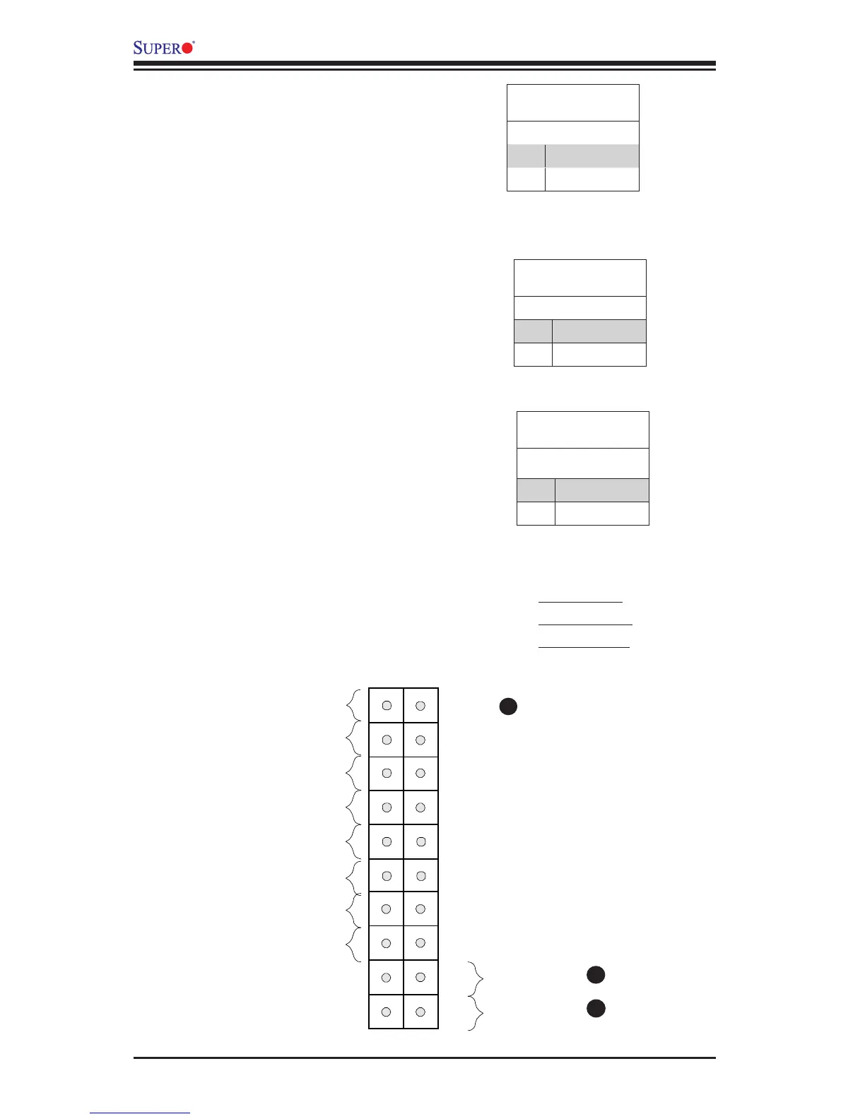
NMI Button
The non-maskable interrupt button
header is located on pins 19 and 20
of JF1. Refer to the table on the right
for pin denitions.
NMI Button
Pin Denitions (JF1)
Pin# Denition
19 Control
20 Ground
Power Button
The Power Button connection is located
on pins1 and 2 of JF1. Momentarily con-
tacting both pins will power on/off the sys-
tem. This button can also be congured
to function as a suspend button (with a
setting in the BIOS - see Chapter 4). To
turn off the power in the suspend mode,
press the button for at least 4 seconds.
Refer to the table on the right for pin
denitions.
Power Button
Pin Denitions (JF1)
Pin# Denition
1 Signal
2 +3V Standby
Reset Button
The Reset Button connection is located
on pins 3 and 4 of JF1. Attach it to a
hardware reset switch on the computer
case to reset the system. Refer to the
table on the right for pin denitions.
Reset Button
Pin Denitions (JF1)
Pin# Denition
3 Reset
4 Ground
A. NMI Button
B. Reset Button
C. PWR Button
A
B
Power Button
OH/Fan Fail LED