Chapter 2: Installation
2-31
T-SGPIO1
3-SGPIO1
7
1
3-SGPIO2
T-SGPIO2
I-SATA5
I-SATA4
I-SATA3
I-SATA2
I-SATA1
I-SATA0
JPTM1
SAS0
SAS1
SAS2
SAS3
SAS4
SAS5
17
JUSB1617
9
21
JFPAUDIO
JSTBY
1
3
B81
B82
A81
A82
PCIE4
JPCI3
JWF1
1
3
JCOM2
1
5
6
JCOM1
JUSB89
JUSB1011
1
7
JUSB1213
1
CPU1
JUSB45
JUSB23
JKBMS_USB01
JAUDIO1
JLAN2_USB67
BT1
+
PCIE1
PCIE2
DIMM2A
DIMM3A
DIMM4A
DIMM1B
DIMM2B
DIMM3B
DIMM4B
DIMM1A
JF1
JD1
JTAG1
6
1
REV:1.01
Tested to Comply
With FCC Standards
FOR HOME OR OFFICE USE
DESIGNED IN USA
MAC
SAS CODE
BAR CODE
JPW2
PCIE6
1
JPI2C1
JBT1
JPW1
1
JSPDIF_OUT
1
JSPDIF_IN
JI2C2
1
JI2C1
1
1
JL1
1
JCF1
1
JOH1
DP2
31
JPME1
JPAC1
JWD1
JVR2
JPL2
JPUSB1
JPME_DBG
4
FANA
FAN3
FAN1
FAN2
FAN4
MH3
MH7
MH4
MH8
MH1
MH9
MH6
MH5
H*
Pin1:RAID_KEY_PCH
JRK1
Pin2:Ground
Pin3:PCH_DYN_SKU
:TPM/PRO80
OFF:By BIOS
JFPAUDIO_EN1
ON:Force Enable
USB3.0 2/3
2-3:Normal
1-2:BIOS recovery
JPBIOS1
JPME_DBG
1-2:ME Debug
2-3:Normal
JPME1
1-2:ME recovery
2-3:Normal
SLOT6 PCI-E 3.0 X16
SLOT4 PCI-E 3.0 X16
SLOT2 PCI-E 3.0 X4(IN X8)
SLOT1 PCI-E 2.0 X4(IN X8)
1-2:ENABLE
2-3:DISABLE
JPT1
USB12/13
USB10/11
COM1
1-2:ENABLE
JPAC1:AUDIO
2-3:DISABLE
AUDIO FP
HD AUDIO
USB6/7
USB3.0 0/1
USB2/3
USB0/1
X9SRA-6
1-2 ENable
Power
Flash
KB/MOUSE
JPUSB1:USB Wake Up
2-3 Disable
PWRI2C
JF1
RST
ON
PWR
PWR
FF
FAIL
HDD
NIC
1
2
NIC
OH
LED
NMI
PWR
X
PWR LED
SPEAKER
1-3:
4-7:
JD1:
2-3:NMI
JWD1:Watch Dog
1-2:RST
LAN1
LAN2
USB4/5
INTRUSION
CHASSIS
OFF: SLAVE
ON: MASTER
JCF1:Compact Flash
Compact
USB8/9
Wake on Lan
COM2
OFF:DISABLE
ON: ENABLE
I2C bus for PCI slot
JI2C1/JI2C2
SLOT5 PCI-E 2.0 X1
SLOT3 PCI 33MHZ
CLOSE 1st
OPEN 1st
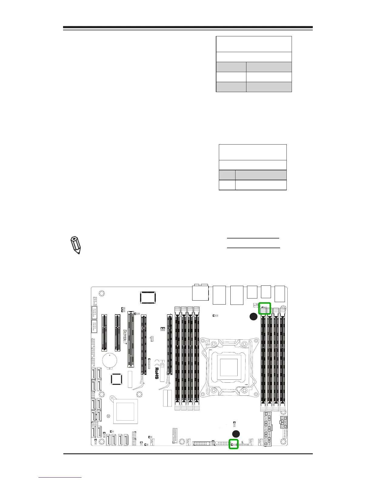
A
A. Watch Dog Reset
B. USB 0/1 Wake-up
Watch Dog Reset (JWD1)
Watch Dog (JWD1) is a system moni-
tor that can reboot the system when a
software application hangs. Close Pins
1-2 to reset the system if an applica-
tion hangs. Close Pins 2-3 to generate a
non-maskable interrupt signal for the ap-
plication that hangs. See the table on the
right for jumper settings. Watch Dog must
also be enabled in the BIOS.
Watch Dog
Jumper Settings
Jumper Setting Denition
Pins 1-2 Reset (default)
Pins 2-3 NMI
Open Disabled
USB Wake-Up (JPUSB1)
Use the jumper JPUSB1 to "wake-up"
your system by pressing a key on a USB
keyboard or clicking the USB mouse con-
nected to the backpanel USB Ports 0/1.
JPUSB1 is used together with a USB
Wake-Up feature in the BIOS. Enable this
jumper and the USB support in the BIOS to
wake up your system via USB devices.
Note: When the USB is set to Enabled
in the BIOS, and JPUSB1 is set to Dis-
abled, remove the USB devices from
backpanel USB Ports 0/1 before the
system goes into the standby mode.
JPUSB1 (Backplane USB
0/1 Wake-up Enable)
Pin# Denition
1-2 Enabled (Default)
2-3 Disabled
B