Chapter 2: Installation
2-25
T-SGPIO1
3-SGPIO1
7
1
3-SGPIO2
T-SGPIO2
I-SATA5
I-SATA4
I-SATA3
I-SATA2
I-SATA1
I-SATA0
JPTM1
SAS0
SAS1
SAS2
SAS3
SAS4
SAS5
17
JUSB1617
9
21
JFPAUDIO
JSTBY
1
3
B81
B82
A81
A82
PCIE4
JPCI3
JWF1
1
3
JCOM2
1
5
6
JCOM1
JUSB89
JUSB1011
1
7
JUSB1213
1
CPU1
JUSB45
JUSB23
JKBMS_USB01
JAUDIO1
JLAN2_USB67
BT1
+
PCIE1
PCIE2
DIMM2A
DIMM3A
DIMM4A
DIMM1B
DIMM2B
DIMM3B
DIMM4B
DIMM1A
JF1
JD1
JTAG1
6
1
REV:1.01
Tested to Comply
With FCC Standards
FOR HOME OR OFFICE USE
DESIGNED IN USA
MAC
SAS CODE
BAR CODE
JPW2
PCIE6
1
JPI2C1
JBT1
JPW1
1
JSPDIF_OUT
1
JSPDIF_IN
JI2C2
1
JI2C1
1
1
JL1
1
JCF1
1
JOH1
DP2
31
JPME1
JPAC1
JWD1
JVR2
JPL2
JPUSB1
JPME_DBG
4
FANA
FAN3
FAN1
FAN2
FAN4
MH3
MH7
MH4
MH8
MH1
MH9
MH6
MH5
H*
Pin1:RAID_KEY_PCH
JRK1
Pin2:Ground
Pin3:PCH_DYN_SKU
:TPM/PRO80
OFF:By BIOS
JFPAUDIO_EN1
ON:Force Enable
USB3.0 2/3
2-3:Normal
1-2:BIOS recovery
JPBIOS1
JPME_DBG
1-2:ME Debug
2-3:Normal
JPME1
1-2:ME recovery
2-3:Normal
SLOT6 PCI-E 3.0 X16
SLOT4 PCI-E 3.0 X16
SLOT2 PCI-E 3.0 X4(IN X8)
SLOT1 PCI-E 2.0 X4(IN X8)
1-2:ENABLE
2-3:DISABLE
JPT1
USB12/13
USB10/11
COM1
1-2:ENABLE
JPAC1:AUDIO
2-3:DISABLE
AUDIO FP
HD AUDIO
USB6/7
USB3.0 0/1
USB2/3
USB0/1
X9SRA-6
1-2 ENable
Power
Flash
KB/MOUSE
JPUSB1:USB Wake Up
2-3 Disable
PWRI2C
JF1
RST
ON
PWR
PWR
FF
FAIL
HDD
NIC
1
2
NIC
OH
LED
NMI
PWR
X
PWR LED
SPEAKER
1-3:
4-7:
JD1:
2-3:NMI
JWD1:Watch Dog
1-2:RST
LAN1
LAN2
USB4/5
INTRUSION
CHASSIS
OFF: SLAVE
ON: MASTER
JCF1:Compact Flash
Compact
USB8/9
Wake on Lan
COM2
OFF:DISABLE
ON: ENABLE
I2C bus for PCI slot
JI2C1/JI2C2
SLOT5 PCI-E 2.0 X1
SLOT3 PCI 33MHZ
CLOSE 1st
OPEN 1st
C
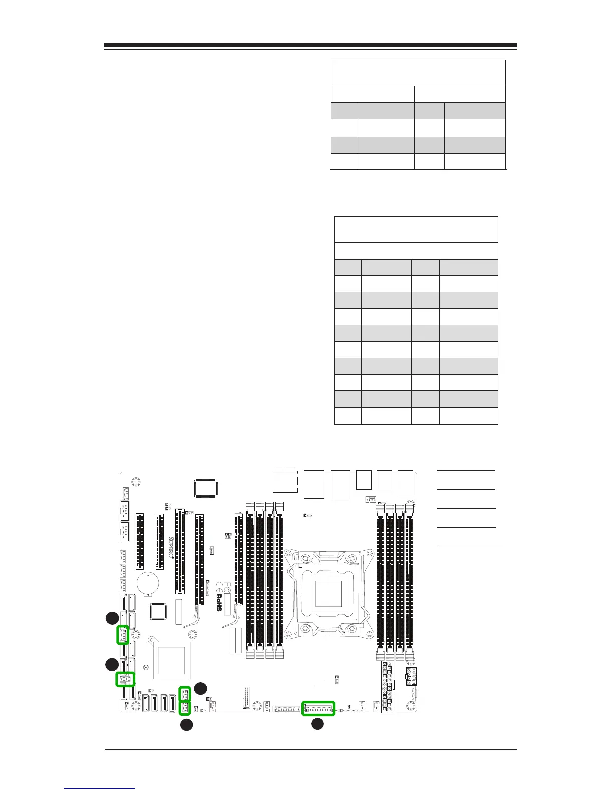
Serial_Link-SGPIO
Pin Denitions
Pin# Denition Pin Denition
1 NC 2 NC
3 Ground 4 DATA Out
5 Load 6 Ground
7 Clock 8 NC
NC: No Connections
A. T-SGPIO 1
B. T-SGPIO 2
C. 3-SGPIO 1
D. 3-SGPIO 2
E. TPM Header
A
B
T-SGPIO 1/2 & 3-SGPIO 1/2 Headers
Two T-SGPIO (Serial-Link General Pur-
pose Input/Output) headers are located
next to the I-SATA Ports on the mother-
board. Additionally, two 3-SGPIO ports
(for SAS) are also located next to USB
8/9 . These headers are used to com-
municate with the enclosure manage-
ment chip in the system. See the table
on the right for pin denitions. Refer to
the board layout below for the locations
of the headers.
Trusted Platform Module Header
Pin Denitions
Pin # Denition Pin # Denition
1 LCLK 2 GND
3 LFRAME 4 No Pin
5 LRESET 6 VCC5
7 LAD3 8 LAD2
9 VCC3 10 LAD1
11 LAD0 12 GND
13 RSV0 14 RSV1
15 SB3V 16 SERIRQ
17 GND 18 CLKRUN
19 LPCPD 20 RSV2
TPM Header (JTPM1)
This header is used to connect a
Trusted Platform Module (TPM), which
is available from a third-party vendor.
A TPM is a security device that sup-
ports encryption and authentication
in hard drives. It enables the moth-
erboard to deny access if the TPM
associated with the hard drive is not
installed in the system. See the table
on the right for pin denitions.
D
E
 Loading...


