3 Measuring
3-3
Continued to next page
④
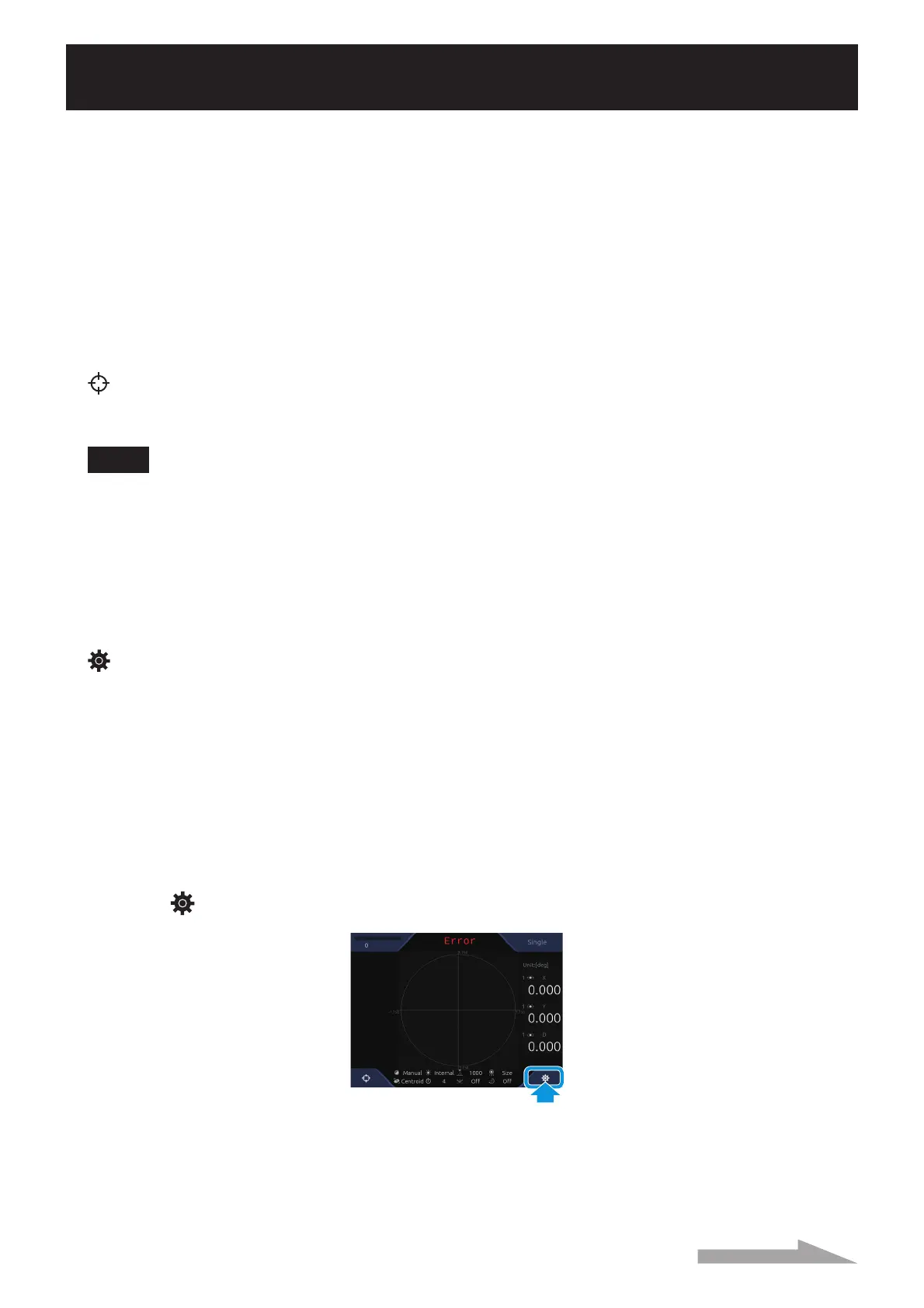
Camera image display
A camera image is displayed.
⑤
Incident light measurement result (absolute value)
Measurement center of each light reception spot and angle (tilting) around the X and Y axis are
displayed.
For the display unit, the one selected in the [Unit] setting (ĺ Page 2-25) is used.
⑥
Incident light measurement result (relative value)
The surface’s angle that is generated with multiple spots is displayed.
⑦
(Zero set) button
Touch this button to de¿ne the light point spot position as the measurement center. Touch this button
again to revert the center point as the measurement center.
NOTE
When >Detect Mode@ (ĺ Page 2-22) is >Center (BIN)@ or >Centroid (GRA<)@, the center position may
change.
⑧
Setting value display
The setting state of the following items is displayed.
LD Adjustment, Light Source, LD Power, Spot Sorting Rules, Detect Mode, Trigger Interval, Mirroring,
and Rotation
⑨
(Settings) button
Touch this button to display the [Settings] screen (ĺ Page 2-2).
Settings of the Measurement Mode
Depending on a measurement mode, the measurement and judgment standards differ.
When changing the measurement mode, conduct the following procedure. For details of setting contents,
see Page 2-15.
1
Touch (Settings) in the measurement screen.
The [Settings] screen is displayed.
 Loading...