4-38 FI SYSTEM
B/Br
Dg
V
“C21” IAT SENSOR CIRCUIT MALFUNCTION
DETECTED CONDITION POSSIBLE CAUSE
High intake air temp. (Low voltage – Low • Dg circuit shorted to ground.
resistance) • B/Br circuit open.
Low intake air temp. (High voltage – High • IAT sensor malfunction.
resistance) • ECM malfunction.
INSPECTION
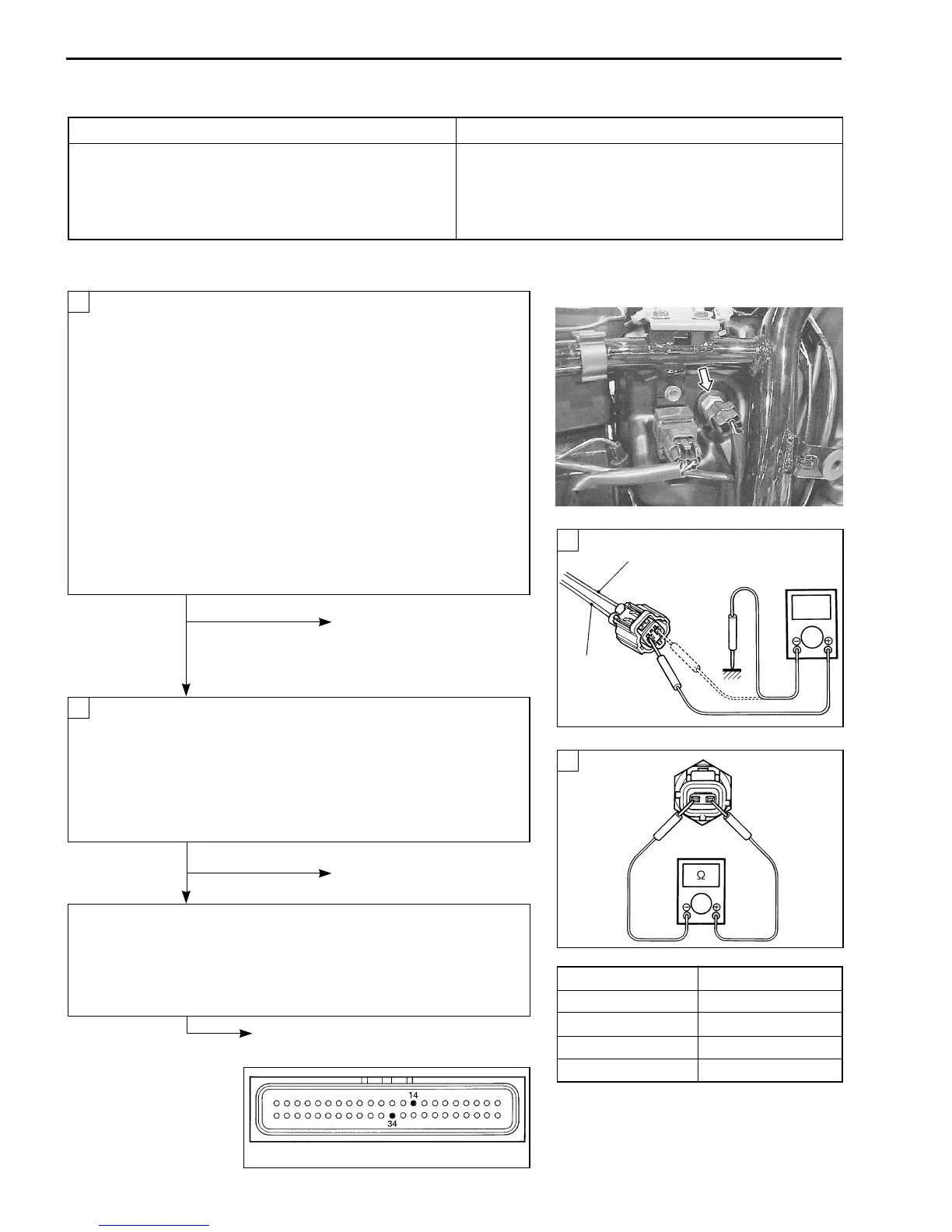
• Remove the right frame side cover. (6-3)
Turn the ignition switch OFF.
Check the IAT sensor coupler for loose or poor contacts.
If OK, then measure the IAT sensor voltage at the wire
side coupler.
Disconnect the coupler and turn the ignition switch ON.
Measure the voltage between Dg wire terminal and
ground.
If OK, then measure the voltage between Dg wire terminal
and B/Br wire terminal.
IAT sensor voltage: 4.5 – 5.5 V
(
+Dg – -Ground
)
+Dg – -B/Br
\ 09900-25008: Multi circuit tester
W Tester knob indication: Voltage (
)
No Loose or poor contacts on
the ECM coupler.
Open or short circuit in the
Dg wire or B/Br wire.
Ye s
Turn the ignition switch OFF.
Measure the IAT sensor resistance.
IAT sensor resistance: Approx. 2.6 k
ΩΩ
ΩΩ
Ω at 20°C (68°F)
(Terminal – Terminal)
\ 09900-25008: Multi circuit tester
V Tester knob indication: Resistance (
ΩΩ
ΩΩ
Ω)
No Replace the IAT sensor
with a new one.
Ye s
Dg or B/Br wire open or shorted to ground, or poor D or X
connection. (4-22)
If wire and connection are OK, intermittent trouble or faulty ECM.
Recheck each terminal and wire harness for open circuit and
poor connection. (4-4)
Replace the ECM with a new one,
and inspect it again.
1
2
1
2
Intake Air Temp. Resistance
20°C( 68°F) Approx. 2.6 kΩ
50°C (122 °F) Approx. 0.8 kΩ
80°C (176 °F) Approx. 0.3 kΩ
110°C (230 °F) Approx. 0.2 kΩ
NOTE:
IAT sensor resistance measurement
method is the same way as that of the EOT
sensor. Refer to page 5-11 for details.
ECM coupler
 Loading...


