18 Synopsys, Inc.
SolvNetPlus
DesignWare
5.60a
March 2020
Setting Up Hardware Components PCIe IP Prototyping Kit Installation Guide
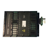
5. Insert the MGB Shelves in the HAPS-80, and tighten the four screws removed in Step 3.
6. In an upward movement, push the RISER1_MGB card into the MGB1 port. Make sure the
RISER1_MGB card is completely inserted.
7. Connect the PCIE-4 MGB to the RISER1_MGB card J2 port. Use the grooves in the MGB shelves to
guide the PCIE-8 paddle board (See Figure 1-7).
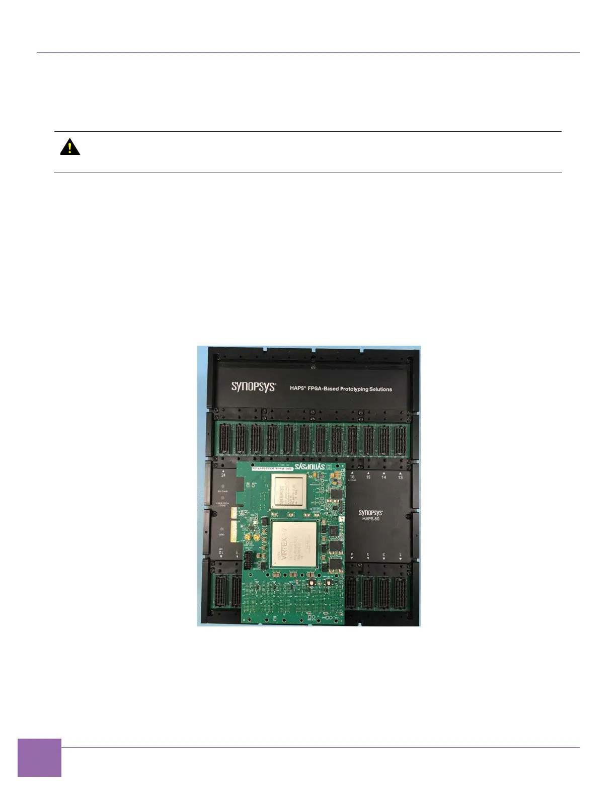
8. Connect the Synopsys PCIe PHY Board to the HAPS-80 board.
If you're using a C10 PHY, use HT3 ports J5-J10 on the HAPS-80 and ports P1-P6 on the C10 PHY to
mechanically connect the boards.
If you're using a E16 PHY, use HT3 ports J5-J10 on the HAPS-80 and ports P1-P6 on the E16 PHY.
Figure 1-10 illustrates this connection using a C10 PHY board as an example.
Figure 1-10 Connection of C10 PHY to HAPS-80
If you are using E32 PHY, use HT3 ports 20, 21, 22 and 23 on the HAPS-80 and HT3 ports 4 ,3 ,2 and 1
respectively, on the E32 PHY. And also ports 8, 9, 10 and 11 on the HAPS-80 and ports 5, 6 ,7 and 8,
respectively, on the E32 PHY to mechanically connect the boards.
Figure 1-16 and Figure 1-22 illustrates this connection using a E32 PHY board.
To avoid damaging the HAPS-80 and RISER1_MGB card, make sure you disconnect the
RISER1_MGB card from the HAPS-80 before removing the MGB Shelves.