Synopsys, Inc. 21
SolvNetPlus
DesignWare
5.60a
March 2020
PCIe IP Prototyping Kit Installation Guide Setting Up Hardware Components
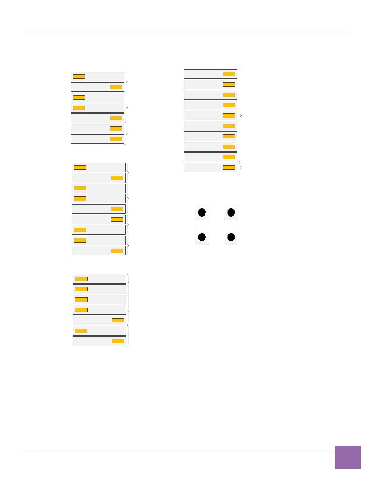
Figure 1-12 ARC SDP DIP Switches Configuration
4. Complete the following hardware power-up sequence to ensure proper inter-board communication.
a. Power up the HAPS-80 board. Connect the HAPS-80 power supply.
During the power-up sequence, the supervision LEDs (RESET, READY, ALERT, and PWR)
change color. After a successful power-up sequence, all LEDs must be green (see Appendix A,
“Status LEDs”, section A.2).
The LED marked UDONE indicates if the FPGA is configured.
1
2
3
4
5
6
7
1
2
3
4
5
6
7
8
9
1
2
3
4
5
6
7
SW2501
OFF ON
SW2503
OFF ON
SW2502
OFF ON
SW2504 SW2507
SW2506 SW2505
Start ARC EM6
GPIO [20]
Start AS221 core
#2 GPIO [23]
Start ARC 770
GPIO [21]
Start AS221 core
#1 GPIO [22]
SW2401
OFF ON
ARC EM6
Boot Mode Select
ARC EM6
Boot Mirror Select
ARC EM6
Boot Location
Select
AS221 core #1
Boot Mode Select
AS221 core #1 and core
#2
Boot Mirror Select
AS221 core #1 and core
#2
Boot Location Select
AS221 core #1
Boot Mode Select
ARC 770
Boot Mode Select
ARC 770
Boot Mirror Select
ARC 770
Boot Location
Select
For application purposes
Pre-Bootloader mode of operation