22 Synopsys, Inc.
SolvNetPlus
DesignWare
5.60a
March 2020
Setting Up Hardware Components PCIe IP Prototyping Kit Installation Guide
b. Make sure the ARC SDP SPI DIP switches are arranged in the configuration as shown in
Figure 1-12
c. Power up the ARC SDP (AXS101) system board. Connect the other power supply to the 12 V
power connection and turn on the power switch on the side of the connector. The AXI Tunnel
connectivity LEDs must be green and the dual seven segment display must show 40 (see
Appendix A, “Status LEDs”).
d. If the PCIe Endpoint device you are using requires a power source, connect it.
e. Power up the PCIe Backplane board by turning on the ATX power supply.
f. The HAPS-80 board LED1 turns green to indicate the PCIe link connection (see Appendix A,
“Status LEDs”, section A.2).
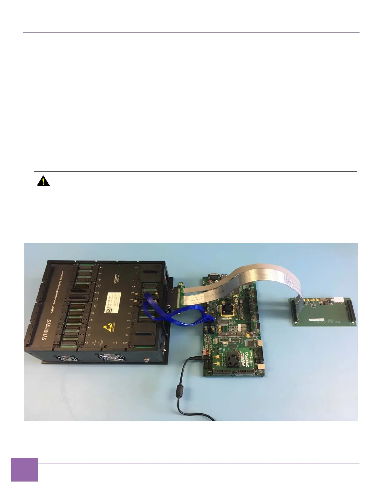
Figure 1-13 illustrates the assembled PCIe Root Complex IP Prototyping Kit using the Xilinx PHY.
Figure 1-14 illustrates the assembled PCIe Root Complex IP Prototyping Kit using the C10 PHY Board.
Figure 1-13 PCIe Root Complex IP Prototyping Kit Setup Using the Xilinx PHY
If the UDONE LED does not turn green within 20 seconds, the FPGA is not properly
configured. Check the following items:
■
Make sure you are using the SD card containing the HAPS-80 FPGA build. For more
information on how to load the HAPS-80 FPGA build into the SD card, see chapter
“Loading HAPS-80 FPGA Build” in the DesignWare PCIe IP Prototyping Kit User Guide.