N770-05-00 2 I56-480-03
Also, follow other applicable NFPA standards, local codes
and the requirements of the authority having jurisdiction.
Failure to follow these directions may result in failure of the
device to report a waterflow condition. System Sensor is
not responsible for devices that have been improperly
installed, tested or maintained.
1. Mount the detector where there is adequate clearance
for installation and removal and a clear view of it for in-
spection. See Figure 1 for mounting dimensions.
2. Locate to protect from damage, 6-7 feet above the floor.
3. On horizontal runs, position the detector on top of the
pipe or on the side of it. Do not mount it upside down
because condensation may collect in the housing and
impair the operation of the detector.
For vertical flow applications, mount detector on pipe
where upflow conditions exist. Failure to do so may pre-
vent unit from operating properly.
4. Mount detector at least 6 inches from a fitting which
changes the direction of the water flow, or no closer than
24 inches from a valve or drain.
5. BE SURE DIRECTION-OF-FLOW ARROW MATCHES AC-
TUAL DIRECTION OF FLOW IN THE PIPE.
Mounting Instructions
1. The WFDT and WFDTH waterflow detectors are de-
signed to fit only the appropriate tee fitting.
NOTE: Leg of tee perpendicular to flow of water must
have a 1" NPT thread. Do not use a reducer to
achieve the correct thread size. Failure to follow
this instruction will result in failure of the detector
to report a waterflow condition.
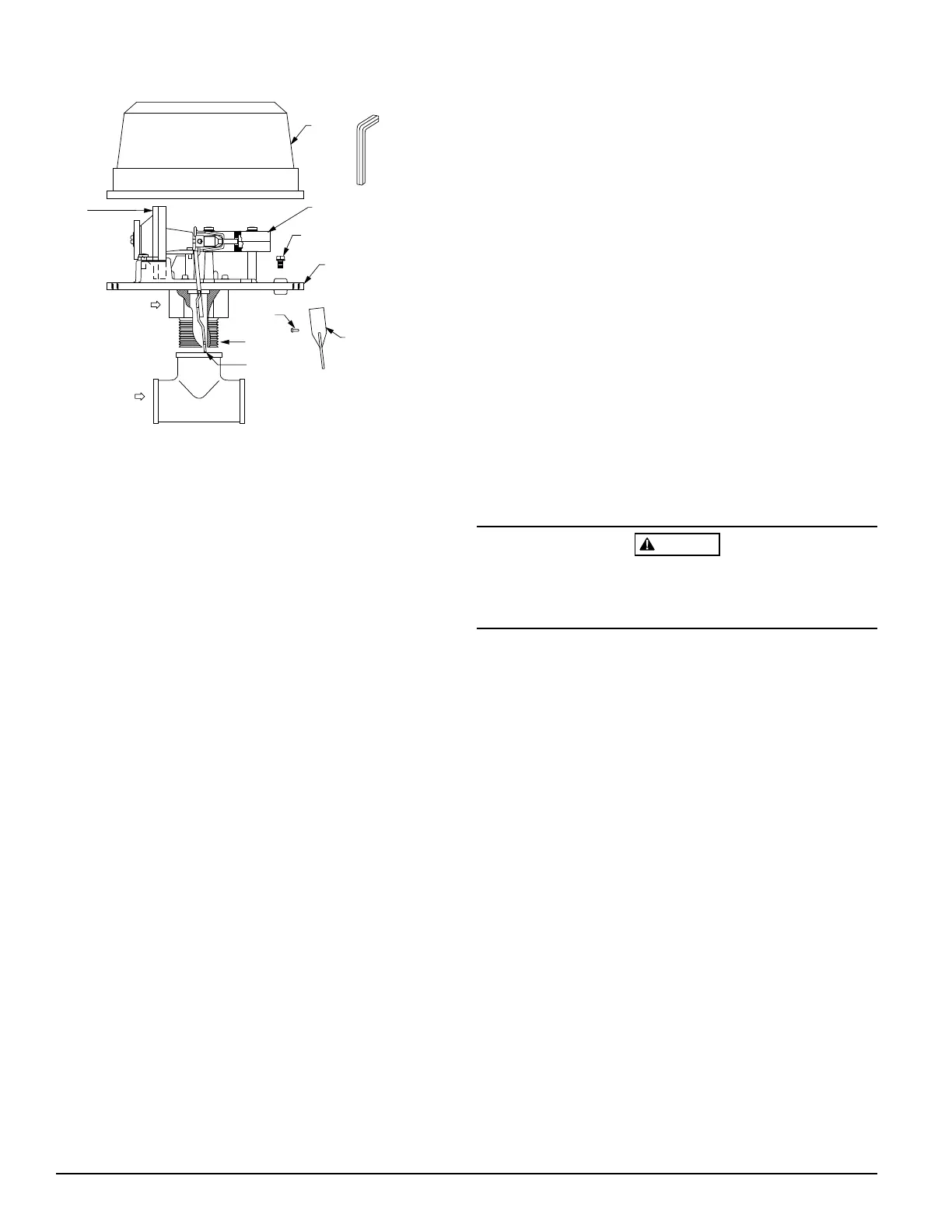
2. WFDT and WFDTH units are shipped without paddles
mounted to the actuator. Select the correct size paddle
for the type of tee being used. Align hole on stem of
paddle with hole on actuator lever. Fasten together using
a #4-40 x 1/4" fillister head screw supplied in bag as-
sembly. See Figure 2. Use only the screw provided with
the unit. Drive screw head through hole in paddle until
it seats to actuator lever surface. No washer is required.
For paddle replacement refer to Maintenance section.
3. Carefully roll the vane opposite the direction of flow and
insert through tee. Thread detector onto tee fitting and
tighten with wrench. Use of thread sealant or tape is rec-
ommended. Use height gage (located at end of paddle
tee) to ensure proper depth of detector on tee fitting. See
Figure 1. Height gage must fit between top of tee fitting
and under side of hex tee adapter. A gap between gage
and tee adapter is acceptable. When correctly installed,
the detector must face in the proper direction of
waterflow and be aligned with the pipe.
4. Remove the metal cover. Move the actuator lever back
and forth to check for binding. If the vane binds, remove
the detector and correct the problem before proceeding.
CAUTION
Be sure the direction-of-flow arrow points in the right direc-
tion, otherwise a waterflow condition will go unreported.
See Figure 2.
Preoperation Testing
1. Fill the sprinkler system with water and check for leaks
around the WFDT or WFDTH. If there is a leak, check to
see that the fittings are tight. If leak persists, drain the
system and remove the detector (see removal instruc-
tions under Maintenance). Check for damaged threads
or cracked fitting. Reinstall the detector and check again
for leaks. Do not proceed until all leaks have been
stopped.
2. Connect an ohmmeter or continuity tester across (COM
and B) terminal switch contacts. The ohmmeter should
show an open circuit, no continuity.
3. Deflect the actuator lever and hold it until the pneumatic
delay shaft releases the switch buttons. The ohmmeter
or continuity tester should show a short circuit after the
delay has elapsed. If there is no delay, check the setting
of the delay adjustment dial.
Figure 2. Assembly diagram:
GROUND
SCREW
(GREEN)
MOUNTING
PLATE
FLOW
WATERFLOW
FILLISTER
HEAD SCREW
ACTUATOR
LEVER
PADDLE
(PADDLE
REPLACEMENT
KIT (P/N PRK9)
COVER
SWITCH ENCLOSURE
(REPLACEMENT
P/N A77-01-02)
DELAY
MECHANISM
(REPLACEMENT
P/N A3008-00)
1″ NPT THREAD
TAMPER PROOF
WRENCH (P/N WFDW)
A78-2134-01
(Cover tamper option is available.)
Technical Manuals Online! - http://www.tech-man.com