N770-03-00 4 I56-394-05
© System Sensor 1996
Three-Year Limited Warranty
System Sensor warrants its enclosed supervisory switch to be free from
defects in materials and workmanship under normal use and service for a
period of three years from date of manufacture. System Sensor makes no
other express warranty for this supervisory switch. No agent, representa-
tive, dealer, or employee of the Company has the authority to increase or
alter the obligations or limitations of this Warranty. The Company’s obli-
gation of this Warranty shall be limited to the repair or replacement of any
part of the supervisory switch which is found to be defective in materials
or workmanship under normal use and service during the three year pe-
riod commencing with the date of manufacture. After phoning System
Sensor’s toll free number 800-SENSOR2 (736-7672) for a Return Authori-
zation number, send defective units postage prepaid to: System Sensor,
Repair Department, RA #__________, 3825 Ohio Avenue, St. Charles, IL
60174. Please include a note describing the malfunction and suspected
cause of failure. The Company shall not be obligated to repair or replace
units which are found to be defective because of damage, unreasonable
use, modifications, or alterations occurring after the date of manufacture.
In no case shall the Company be liable for any consequential or incidental
damages for breach of this or any other Warranty, expressed or implied
whatsoever, even if the loss or damage is caused by the Company’s negli-
gence or fault. Some states do not allow the exclusion or limitation of inci-
dental or consequential damages, so the above limitation or exclusion may
not apply to you. This Warranty gives you specific legal rights, and you
may also have other rights which vary from state to state.
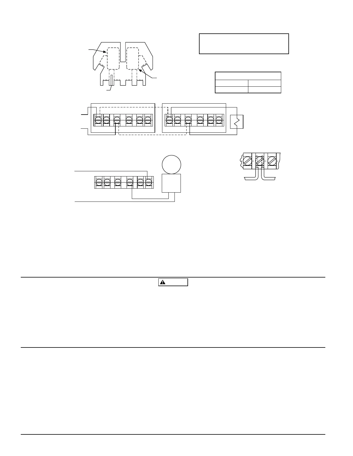
Top View
Switch 1
COM
COM
ABB A
Switch 2
CONTACT RATINGS
125/250 VAC
24 VDC
10 AMPS
2.5 AMPS
Sup. Switch
BB
COM COM
Sup. Switch
BB
COM COM
Typical FACP Connection
to nonsilenceable initiating
zone of listed FACP
end-of-line resistor
B
COM
to power source
compatible
with bell
local
bell
Typical Local Bell Connection
Break wire as shown for supervision
of connection. DO NOT allow stripped
wire leads to extend beyond switch
housing. DO NOT loop wires.
Strip Gage
A78-1639-00
Figure 6:
1. Alarms generated by the activation of the actuating lever
may not be received by a central station if telephone or
other communication lines to the alarm device are out of
service, disabled, or open.
2. Supervisory switch alarm devices have a normal service life
of 10-15 years.
WARNING
The Limitations of Supervisory Switch Alarm Devices
3. Supervisory switches are not a substitute for insurance.
Building owners should always insure property and lives
being protected.
NOTE: Common and B connections will
close when valve moves 1/5 of its
total travel distance.
Technical Manuals Online! - http://www.tech-man.com