18
| Installation
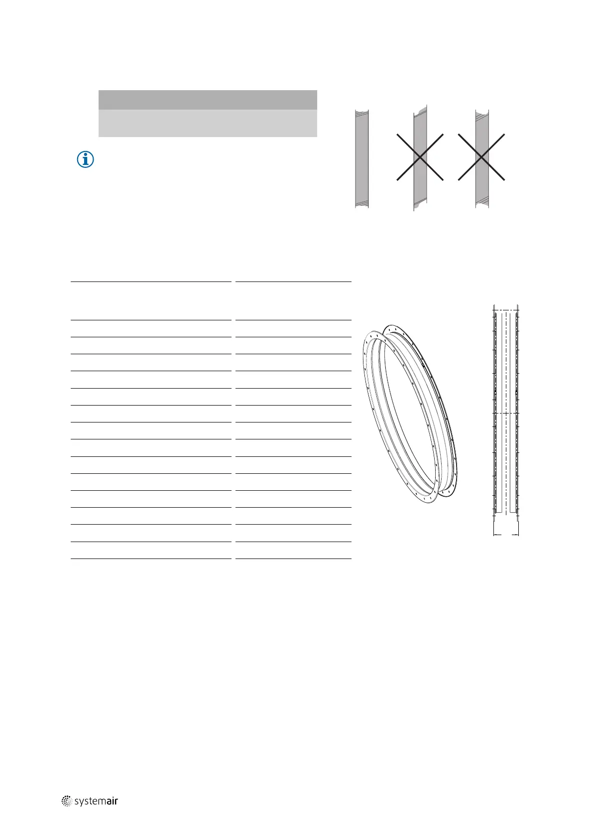
7.9.3 Installation of flexible connections
Important
Increasing noise emission
♦ Do not install the flexible connections at an angle.
Note:
When fitting the flexible connections, make sure that
they are fitted according to the installation length
(Table 15 Flexible connections — Installation length,
page 18), without compression or tensile strain. They
must not be used to compensate any lack of precision
in the assembly.
Table 15 Flexible connections — Installation length
EV (-25...70°C) EVH (400°C/2h)
Size
LB full
length
[mm]
LE
Installation
length [mm]
LB Overall
length
[mm]
LE
Installation
length [mm]
315
157 (+/-5)
LB — 10
147 (+/-5)
LB — 10
355
157 (+/-5)
LB — 10
147 (+/-5)
LB — 10
400
157 (+/-5)
LB — 10
147 (+/-5)
LB — 10
450
157 (+/-5)
LB — 10
147 (+/-5)
LB — 10
500
157 (+/-5)
LB — 10
147 (+/-5)
LB — 10
560
157 (+/-5)
LB — 10
147 (+/-5)
LB — 10
630
157 (+/-5)
LB — 10
147 (+/-5)
LB — 10
710
157 (+/-5)
LB — 10
147 (+/-5)
LB — 10
800
157 (+/-5)
LB — 10
147 (+/-5)
LB — 10
900
157 (+/-5)
LB — 10
147 (+/-5)
LB — 10
1000
157 (+/-5)
LB — 10
147 (+/-5)
LB — 10
1120
157 (+/-5)
LB — 15
147 (+/-5)
LB — 15
1250
157 (+/-5)
LB — 15
147 (+/-5)
LB — 15
1400
157 (+/-5)
LB — 15
200 (+/-5)
LB — 15
1600
157 (+/-5)
LB — 15
200 (+/-5)
LB — 15
7.9.4 Installation silencer
♦ Ensure correct installation of the silencer.
• This can cause damage to the bearings or other parts of the fan.
• The duty point may not be reachable.
• The fan may make noise.
♦ Ensure a direct, smooth and constant air flow to the device. Ensure a free exhaust, see the following pictures.
♦ To reduce transmission of vibration to the duct system, we recommend flexible connections from our accessory
range, see 5.2.3 Accessories, page 8.
| 004