AlarmExplanation
Dothefollowing
Rot
Indicatesarotormalfunction.
Thealarmisdisplayedinthecontrolpanel.
•Iftherotatingheatexchangerhasstopped.Check
therotorbelt.Seechapter5.7
•Iftheheatexchangerisstillrotating,checkthatthe
quickconnectorforthesensorisconnectedand
thatthereisanairgapof5-10mmbetweenthe
sensorandthemagnet.
Adjustthegapifnecessary.
Ifthealarmpersists,therotorsensormaybefaulty.
Contactyourinstallationcompanyorplaceof
purchase.
PbFail
Errorinconnectionwithrelay
cardfortheelectricalre-heater(if
installedandactivated).
Theoverheatprotectionsensor,
automaticreset(ET2)maybe
triggeredduetohightemperature.
Thealarmisdisplayedinthecontrolpanel.
Theheaterwillnotbeactivated.
FortriggeredET2,wait10–15min.Iftheerror
remains,contactyourinstallationcompanyorplace
ofpurchase.
Temp
Malfunctioninoneormoreofthe
temperaturesensors.
Thealarmisdisplayedinthecontrolpanel.
Contactyourinstallationcompanyorplaceof
purchase.
Filter
Timeforlterchange.
Thealarmisdisplayedinthecontrolpanel.
ChangelteraccordingtotheinstructionsintheUser
Manual.
LowSS
Indicateslowsupplyair
temperature
Thealarmisdisplayedinthecontrolpanel.
Ifwaterreheaterisconguredandfrostprotection
havefailed,thenanextrasecurityfunctionistriggered
whensupplyairtemperatureislowerthan5°Cand
outdoorairtemperatureisbelow0°C.
RH
Indicatesmalfunctionofinternal
relativehumiditysensor.
Thealarmisdisplayedinthecontrolpanel.
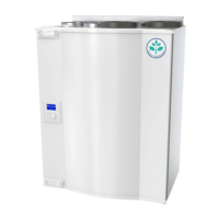
8.2Typelabel
Beforecallingyourservicerepresentative,makeanoteofthespecicationandproductionnumberfrom
thetypelabel,whichcanbefoundonthesideoftheunits,nexttotheexternalconnections.
SAVEVTR200/BUserManual
208062
15
SystemairSverigeAB
 Loading...
