Page 58
Technical data
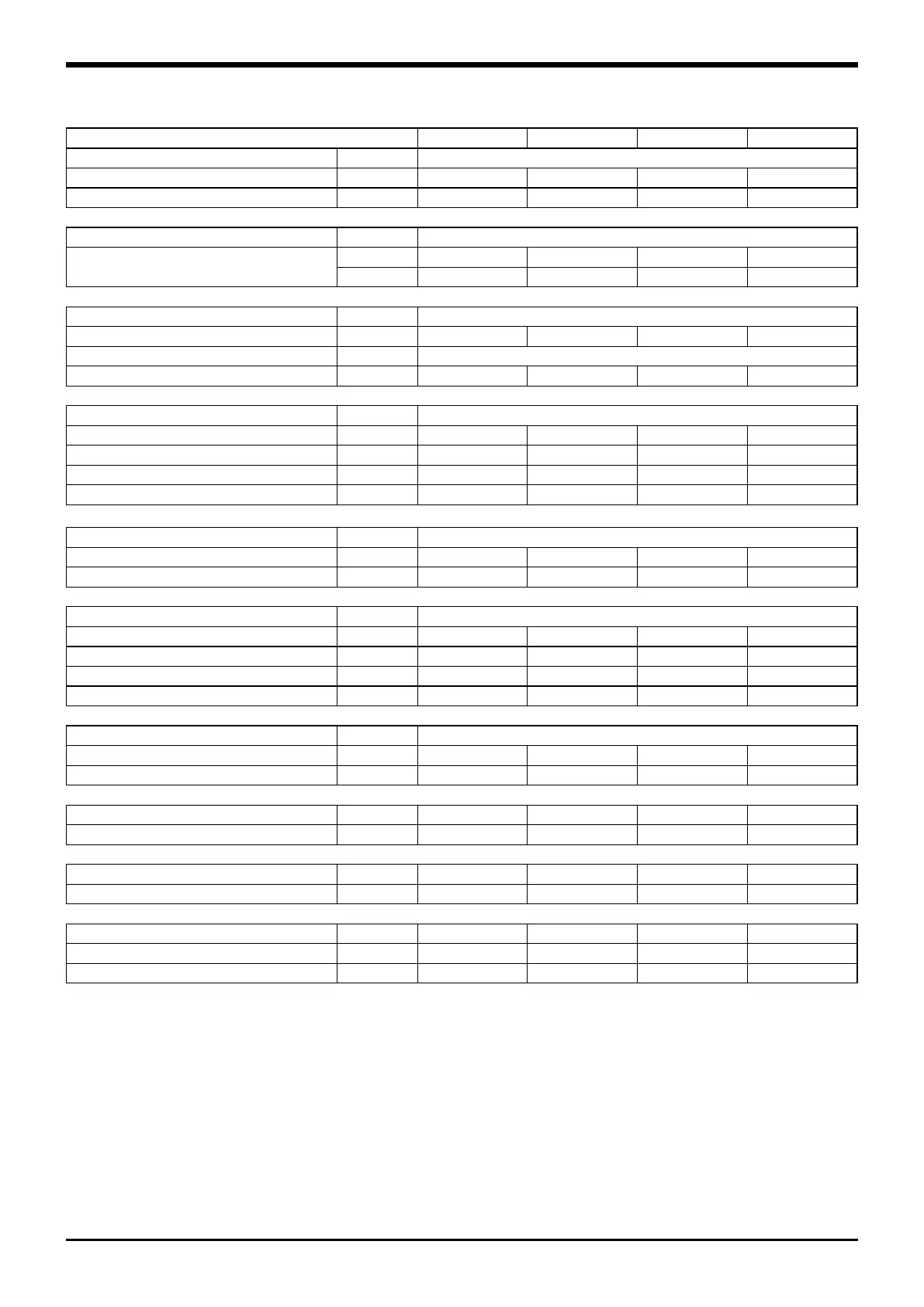
VLR 904 1004 1104 1204
Power supply V/ph/Hz 400 (±10%) / 3 / 50
Number of circuits 2 2 2 2
Capacity steps % 28-50-78-100 25-50-75-100 23-50-73-100 25-50-75-100
Refrigerant
Type / GWP R410A / 2.088
Charge 1/2
(1)
kg 15/15 17/17 18/18 18/18
tCO
2
eq 31,3/31,3 35,5/35,5 37,6/37,6 37,6/37,6
Compressor
Type Scroll
Number 4 4 4 4
Start-up type Direct
N°of loading stages 0/100 0/100 0/100 0/100
Evaporator
Type Plate
Number 1 1 1 1
Water flow rate l/s 10,9 12,0 13,4 14,7
Pressure drop kPa 23,1 27,7 34,4 41,7
Water volume l 25,2 25,2 25,2 25,2
Hydraulic connections
Type Threaded Gas Male
Inlet diameter inch 3” 3” 3” 3”
Outlet diameter inch 3” 3” 3” 3”
Recovery condenser
Type Plate
Number 1 1 1 1
Water flow rate l/s 13,8 14,8 16,7 18,6
Pressure drop kPa 36,6 42,5 53,5 66,4
Water volume l 25,2 25,2 25,2 25,2
Hydraulic connections
Type Threaded Gas Male
Inlet diameter inch 3” 3” 3” 3”
Outlet diameter inch 3” 3” 3” 3”
Weights
Shipping weight kg 1916 1965 1980 1984
Operating weight kg 1966 2015 2030 2034
Additional Weights
ELN versions kg 35 40 40 40
HSE*/HPF** versions kg 40 40 40 40
Dimensions
Length mm 4300 4300 4300 4300
Width mm 1100 1100 1100 1100
Height mm 2300 2300 2300 2300
(1) The refrigerant value are indicative values for standard units. The actual data are indicated on the unit label.
(*) High Efficiency Units (HSE) with inverter fans.
(**) HPF Units with high static pressure fans.

 Loading...


