Page 72
VLS-GB.indd 73 17-06-2009 15:56:48
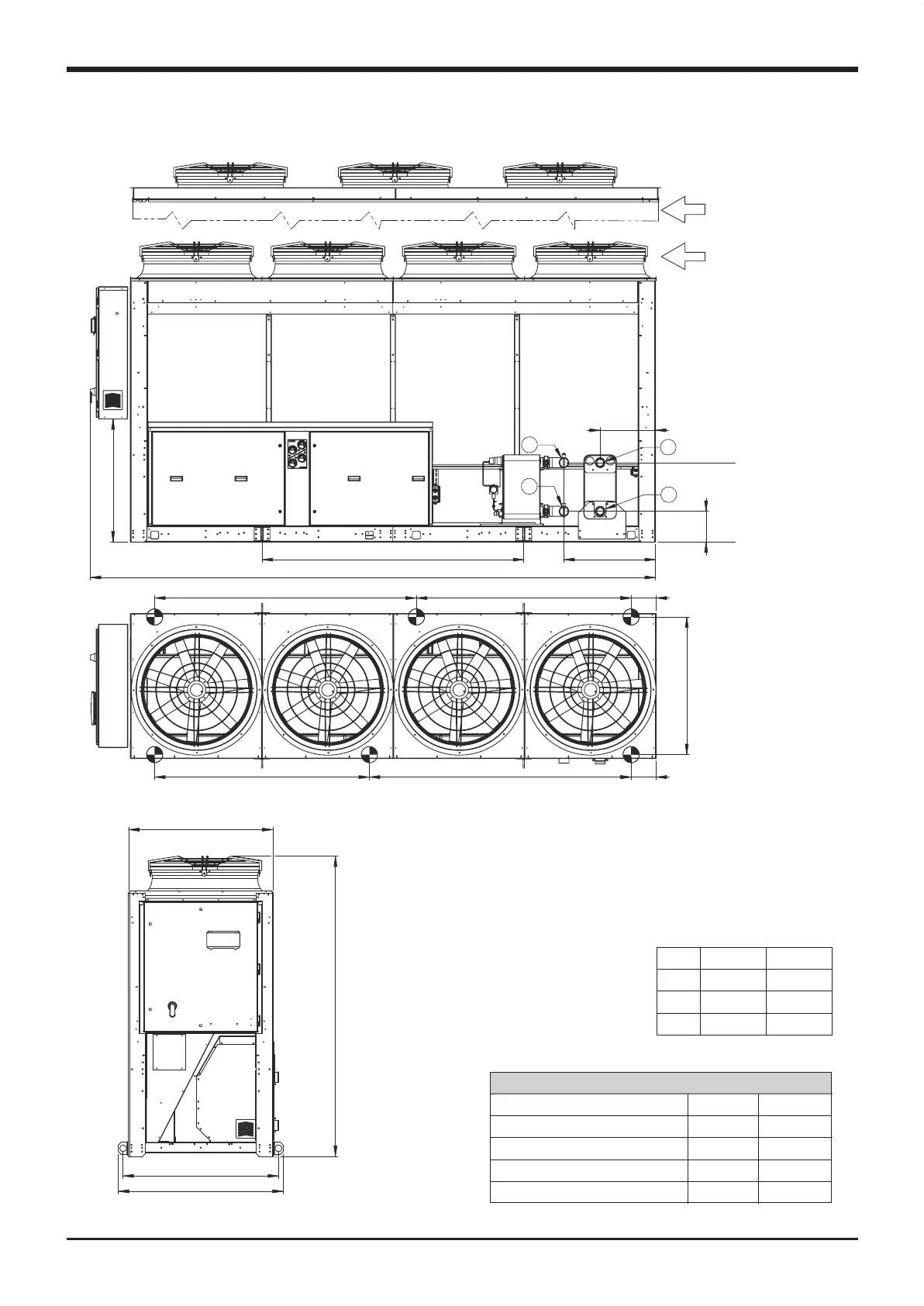
Technical data
1044
19016291985
19019851629
4300
934
L
H1
H2
420
1985 LIFT
D
C
A
B
4 FANS for 904-1204
3 FANS for 704-804
1179 LIFT
1100
2300
1249
VLR 704-1204 BLN/LN/ELN/HT
704-804
273
602
694
H1
H2
L
904-1204
213
840
720
WATER CONNECTIONS
704-804 904-1204
WATER OUTLET “A” 2” 1/2 M 3” M
WATER OUTLET (recover) “B” 2” 1/2 M 3” M
WATER INLET “C” 2” 1/2 M 3” M
WATER INLET (recover) “D” 2” 1/2 M
3” M
VLS-GB.indd 72 17-06-2009 15:56:48

 Loading...


