PAGE
Section 4 • Installation Guide
4.1 The S4.3 Controller
NOTE: Some configuration and set-up
options may require removal of the top
cover of the S4.3 Controller. Before
installing the S4.3 Controller, refer to:
- Section 5.22 Optional Operating Modes
- Section 5.51 Paging Inhibit
- Section 5.6 Configuring the Pre-Out
Sockets
and carry out any necessary internal
setting or adjustments.
Disconnect the mains supply to the
Controller before removing the top cover.
4.11 Source Connections
Connect LINE LEVEL sources (CD player,
tuner, etc.) to the S4.3 Controller’s rear
panel as follows.
a) Using shielded PHONO to PHONO cables,
connect the source’s output to the
corresponding input on the S4.3
Controller as detailed in the following
table:
Tuner
➠
Input 1
CD player
➠
Input 2
Tape Deck/Sat. Receiver/
Cable
➠
Input 3
DVD/VCR/CD 2/Tuner 2
➠
Input 4
Be sure to observe correct channel
continuity from source to S4.3 Controller.
The S4.3 Controller’s PHONO inputs are
labelled for easy identification with Left
Channel connections on the top row and
Right Channel connections on the bottom
row.
NOTE 1: The S4.3 Controller does not
accept a phono cartridge’s output
directly. If required, use a separate phono
preamp (such as QED Discsaver) to boost
the phono signal to line level.
NOTE 2: To simplify system operation,
we strongly suggest using only FIXED
LEVEL source outputs to the S4.3
Controller. If no FIXED LEVEL outputs are
available, use variable outputs but make
sure that the source component’s level
control is turned up sufficiently but not
so high as to overload the S4.3
Controller’s inputs.
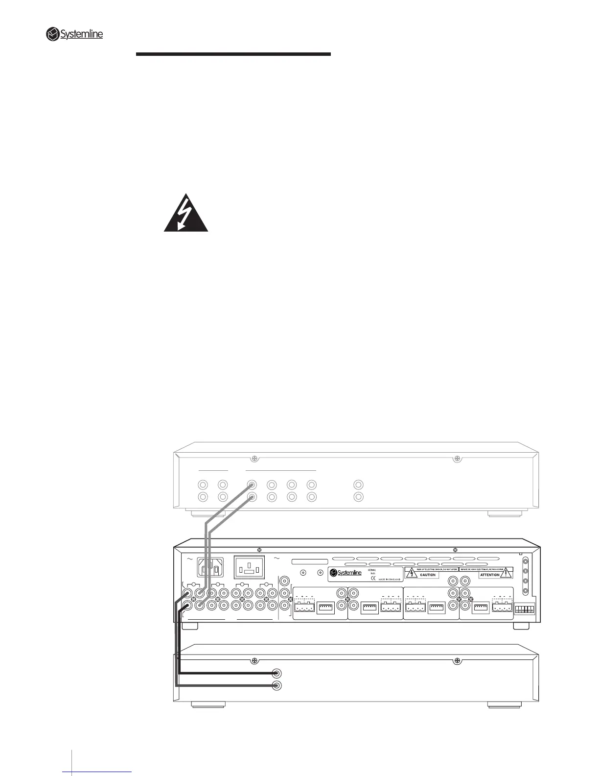
TUNER CD AUX1 AUX2
INPUTSTAPE MONITOR
IN OUT LINE OUT
OUTPUT
RIGHT
LEFT
PREAMPLIFIER
TUNER
Tuner connected to Source 1 input with optional pass-through to preamp for shared use with separate system.
4
3
2
DATA
DATA
RC-5
N/C
AUDIO IN
AUDIO
OUT
IN
RIGHT
INPUTS
LEFT
OUT IN
OUT
IN
OUT
IN OUT
ZONE B
SPEAKERS
RIGHTLEFT
DATA
ZONE C
WE1
WE2
WE3
WE4
TX-FORMAT
ZONE A
SPEAKERS
RIGHT
LEFT
SPEAKERS
RIGHTLEFT
SPEAKERS
RIGHT
LEFT
DATA
T
X
O
U
T
P
U
T
S
1
ZONE D
S4.3 MUTI-ROOM
CONTROL
LINK
IN OUT
230V AC
50Hz
POWER CONSUMPTION: 430W MAX
PRE/LINE-OUTPRE/LINE-OUT
PRE/LINE-OUT
PRE/LINE-OUT
TRIGGER
PAGING
AC OUTLET
230V 50Hz
SWITCHED TOTAL:
460W MAX
123456
123456 123456 123456
123456
11