PAGE
Section 5 • System Set-up
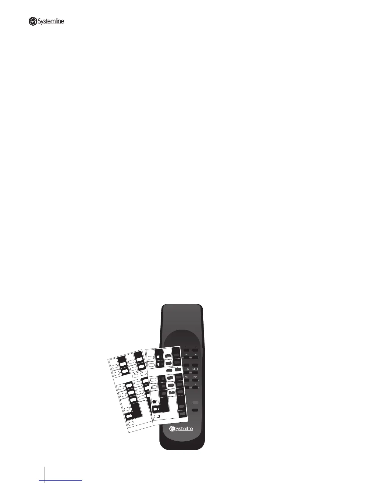
d) Place the appropriate Set-up Card over the
RHS’s pushbuttons.
e) With the RHS pointing at the DMS module,
enter “Set-up” mode by pressing the Set-
Up buttons (RANDOM and DISC buttons)
as indicated on the overlay card and
holding them depressed for a few seconds
until “Set?” is displayed. This indicates that
the system is ready to receive source set-up
information.
f) Push the desired command code button of
the input you want to set. You may select
any required combination of brands, but
remember:
• The appropriate switch within translator
card switch SW1 must be configured for
the code bank (page) holding the code for
the component for each input. Refer to
Section 5.22.
• for each input you must use the correct
overlay card for the configured code bank;
i.e. Card 1 for Page 1 and Card 2 for Page 2.
• if you are using two CD players or two
tuners, they must be different brands.
Zone A's DMS will display the following
characters to indicate your choice of
custom command configuration.
Bank 1 Bank 2
Set Up CardSet Up Card
A = RC-5 Tuner Rotel Tuner
B = RC-5 CD Rotel CD
C = RC-5 VCR RC-5 Tuner2
D = RC-5 Tape Rotel Tape
E = Sony Tuner Onkyo Tuner
F = Sony CD Onkyo CD
G = Sony CD2 Sony Tuner2
H = Sony Tape Onkyo Tape
I = Pioneer Tuner Technics Tuner
J = Pioneer CD Technics CD
K = Pioneer CD2 Pioneer Tuner2
L = Pioneer Tape Technics Tape
M = Yamaha Tuner NAD Tuner
N = Yamaha CD NAD CD
O = Panasonic VCR Yamaha Tuner2
P = Yamaha Tape NAD Tape
Q = Denon CD Luxman CD
R = Sony VCR Toshiba DVD
S = Denon Tape Luxman Tape
T = Denon Tuner Luxman Tuner
U = Sony MiniDisc No Code
V = Pace Sat Galaxy Sat
W = Pioneer DVD Sony2 CD2
X = Nokia Sat Jerrold Cable
5.23 Set-up Sequence
a) Refer to 5.22 above - Ensure that switch
SW1 on the S4.3 Controller translator card
has been re-configured as necessary if the
codes for any source components are
stored on code bank (page) 2.
b) Locate the DMS module for zone A.
Optional operating modes CANNOT be
changed from any other zone, or even from
zone A’s (optional) keypad. To confirm that
the DMS is connected to zone A, send a
command with the RHS hand held remote
and monitor zone A’s green Code LED on the
S4.3 Controller’s front panel: it will flash
when the S4.3 Controller recognizes and
processes a command.
Ensure that the flood output is disconnected
(remove the link between pins 2 & 3 of the
TX format connector) if set-up is carried out
in the same room as the controller.
NOTE: Any DMS module can be connected
to the zone A data terminal for this
procedure. Even if zone A is equipped with
a wall mounted DMS module, it is probably
more convenient to temporarily disconnect
the data cable from that unit and substitute
another DMS placed near the S4.3
Controller and source components. Make
sure that any DMS used in this set-up
sequence has the circuit board DIP
switches set for zone A. (See Section 4.21
b) for details.)
c) Select any input (tuner, CD etc.) on the RHS
so that the corresponding indication shows
on zone A’s DMS
module.
TUNER
CD
FAV STN PRESETS
STOP SKIP
RANDOM DISC
TAPE/SAT STOP
VIDEO/LD
STOP
PAUSE CHNL
X
VOL
VOL
MUTE
STBY
E
ONKYO
F G
ONKYO
SONY-Tu2
H
ONKYO
I J K
L
TECHN
TECHN
PIO-Tu2 TECHN
M N O
P
NAD
NAD
YAM-Tu2 NAD
Q R
S
LUXMAN
TOSH-Dvd LUXMAN
T
LUXMAN
U
V
V
RCA-SAT
W
SONY2-Cd2
Tuner
A
ROTEL
Dvd
Cd2/Tu2
C
RC-5-Tu2
B
ROTEL
D
ROTEL
Sat
Tape
X
V
U
No Code GLX-Sat
JER-Cab
X
Cd
BANK 2 SET-UP CARD RHS3
PRESS BOTH BUTTONS
TOGETHER & HOLD TO
ENTER/EXIT SET-UP MODE
E
SONY
F G
SONY
SONY-Cd2
H
SONY
I J K
L
PIONEER
PIONEER
PIO-Cd2 PIONEER
M N O
P
YAMAHA
YAMAHA
PAN-Vcr YAMAHA
Q R
S
DENON
SONY-Vcr DENON
T
DENON
U
V
V
RCA-SAT
W
PIONEER-Dvd
Tuner
A
RC-5
Dvd
Vcr/Cd2
C
RC-5-Vcr
B
RC-5
D
RC-5
Sat
Tape
X
V
U
SONY-Md PACE-Sat
NOK-Sat
X
BANK 1 SET-UP CARD RHS3
Cd
PRESS BOTH BUTTONS
TOGETHER & HOLD TO
ENTER/EXIT SET-UP MODE
23